2
Details about the MCM10 module
MCM10
62
System version 1:
Modulating weather-compensated heating
controller with EMS BUS control
One benefit of this system version is the ability of the
modules to communicate to enable heating circuits to be
regulated (WM10 and MM10 function modules) with the
MCM10 module via a common BUS, parallel to
connection J on the MCM10 module (Æ fig. 3, page 59).
This ensures optimum matching of the generated amount
of heat to the actual heat demand of all heating circuits in
the heating system. With this version, the heating system
achieves optimum comfort with maximum energy savings.
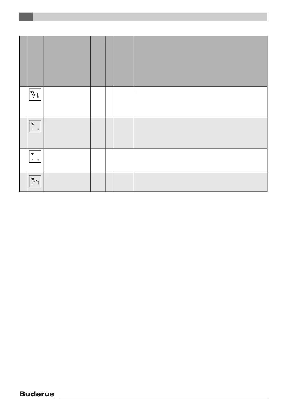
System version
Symbol for
controller connection
Heating controller on
MCM10 master
module
Type
Max. number MCM10
Max. number of boilers
with BUS-enabled
Logamatic EMS
Required accessories with connection to MCM10 (Æ fig. 3, page 59)
1 Modulating weather-
compensated heating
controller with EMS BUS
control.
RC35 4 16 • Outside temperature sensor.
• WM10 low loss header module. The flow temperature sensor (part of the
standard delivery of the WM10) is connected to the WM10 low loss header
module.
• The heating circuit pump is connected to the WM10 module.
2 Modulating 0 - 10 V
controller, regulates acc. to
output.
any 4 16 • Common flow temperature sensor (accessory) on terminals E (only for
internal frost protection function).
• Heating circuit pump (secondary circuit) (Æ fig. 3, [19]) on terminals C, only
with one or several heating circuits without heating circuit pump or with
heating circuits that are not regulated via the building management system.
3 Modulating 0 - 10 V
controller, regulates to flow
temperature.
any 4 16 • Common flow temperature sensor (accessory) on terminals E.
• Heating circuit pump (secondary circuit) (Æ fig. 3, [19]) on terminals C, only
with one or several heating circuits without heating circuit pump or with
heating circuits that are not regulated via the building management system.
4 Heating control unit with
ON/OFF contact.
any 4 16 • Common flow temperature sensor (accessory) on terminals E (only for
internal frost protection function).
• Heating circuit pump (secondary circuit) (Æ fig. 3, [19]) on terminals C.
Tab. 6 System versions overview
0 ... 10V
0 ... 10V