2
Details about the MCM10 module
MCM10
60
I MCM10 no. 1 (master module)
II MCM10 no. 2 (slave module)
III MCM10 no. 3 (slave module)
IV MCM10 no. 4 (slave module)
1…16 Boiler
17 Low loss header
18 Common flow temperature sensor
19 Heating circuit pump
20 Junction box
21 Further subscribers at the heating controller BUS
22 Fuse for heating circuit pump connection
23 Spare fuse
24 Heating circuit
25 Function jumper
A Power supply
B Power supply for additional modules MCM10
C Heating circuit pump connection
D Remote fault indicator connection
E Flow temperature sensor connection
F Outside temperature sensor connection
G External switching contact connection
H ON/OFF contact connection
I Building management system (0 - 10 V interface)
connection
J Heating circuit controller connection (RC35, WM10,
MM10) with EMS BUS switching
K Connection from the previous module MCM10
L Connection to the next module MCM10
M Boiler connection
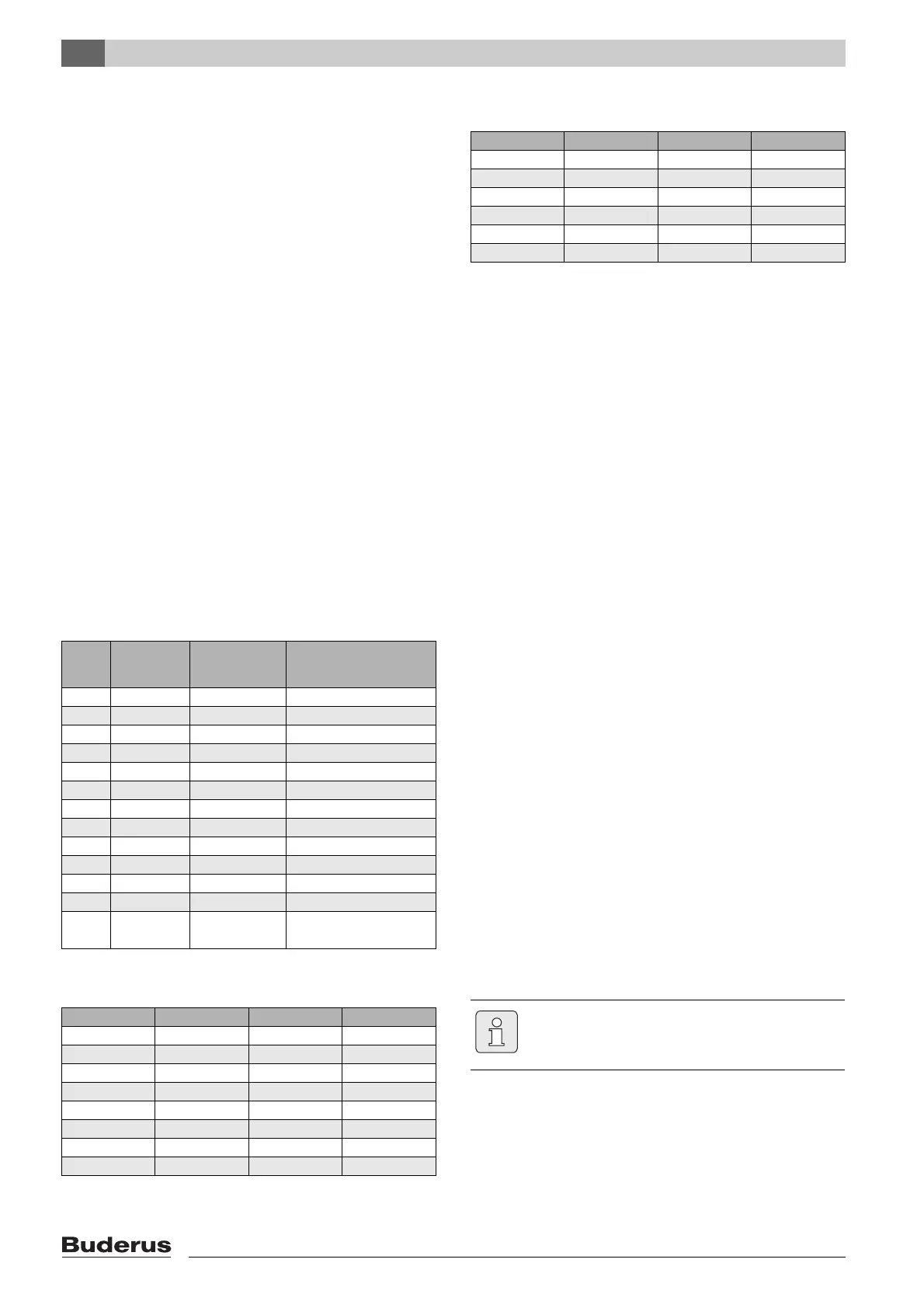
2.6.4 Power supply parameters
2.6.5 Actual values, flow temperature sensor
2.6.6 Actual values, outside temperature sensor
2.7 System integration of the MCM10
2.7.1 Principles of cascade control
When the heating controller signals a heat demand
(Æ tab. 6, page 62) for system versions 1, 2 and 3,
initially one boiler is started and its output raised to its
maximum rated output. Only then will a further boiler be
started.
If excessive heat is being generated, boilers are regulated
in sequence without delay down to their respective
minimum rated output, and then shut down until heat
demand and generation match. With system version 4 all
boilers are shut down simultaneously.
MCM10 module automatically determines the sequence
in which the boilers are controlled. MCM10 module
safeguards an even distribution of the burner hours run for
all boilers. This takes into account the number of hours run
in heating mode as well as in DHW mode. This increases
the boiler service life. If the power supply to the
MCM10 module fails, the hours run meter in the MCM10
module is reset to zero.
If a boiler is not able to start (DHW heating for a directly
connected DHW cylinder, boiler fault, communication
fault with the MCM10 module), another boiler will be
started automatically to cover the heat demand.
2.7.2 Heating control unit for MCM10 cascade
systems
The MCM10 modules control the boilers in accordance
with the heat demand calculated by the heating controller.
For control in accordance with the heat demand, the
MCM10 modules must therefore be installed in
conjunction with a heating controller (Æ fig. 3, page 59,
terminals H, I or J). Subject to the heating controller used,
there are 4 possible system versions (Æ tab. 6, page 62).
One MCM10 module can control up to 4 boilers. By
connecting up to 4 MCM10 modules , up to 16 boilers
can be linked to form a single cascade (Æ fig. 3,
page 59). In this configuration, one MCM10 module
regulates the cascade as the MCM10 master module.
Posi-
tion
Interface Terminals Values
A Input – 230 V AC, max. 16 A
B Output – 230 V AC, max. 16 A
C Output – 230 V AC, max. 250 W
D Output – zero volt, max. 230 V, 1 A
E Input 1-2 NTC (Æ tab. 4)
F Input 3-4 NTC (Æ tab. 5)
G Input 5-6 zero volt
H Input 7-8 24 V DC
I Input 9-10 0 - 10 V DC
J EMS BUS 11-12 –
K EMS BUS 13-14 –
L EMS BUS 15-16 –
M EMS BUS 17-18, 19-20
,
21
-22, 23-24
–
Tab. 3 Power supply parameters
°C Ω °C Ω
20 12490 60 2488
25 10000 65 2083
30 8057 70 1752
35 6531 75 1481
40 5327 80 1258
45 4369 85 1072
50 3603 90 917
55 2986 95 788
Tab. 4 Actual values, flow temperature sensor
°C Ω °C Ω
– 20
97070 10 19900
– 15 72929 15 15708
– 10
55330 20 12490
– 5 42315 25 10000
0 32650 30 8057
5 25388 35 6531
Tab. 5 Actual values, outside temperature sensor
Only 1 heating controller/building
management system can be connected to
ensure the correct function.