2002 Buell X1: Engine 3-45
HOME
Cam Bushing Installation (to Crankcase)
NOTE
Installing and reaming crankcase and gearcase cover bush-
ings may alter the center distances between mating gears
and may result in an increase in gear noise. For quiet-running
gears, the gears should be matched to the center distances.
1. See Figure 3-67. Each cam gear bushing (1), to be
installed in right crankcase half (2), must be positioned in
crankcase bore with its oiling slot at exact top of bore (12
o’clock position).
2. Using an arbor press, install each bushing in its crank-
case bore so that bushing shoulder contacts crankcase
boss.
3. After you install a new bushing in right crankcase half,
ream the bushing to correct size. See CAM BUSHING
REAMING (CRANKCASE).
Cam Bushing Installation (to Gearcase
Cover)
NOTE
For all cam bushings except rear intake, see steps 1 and 2.
For rear intake cam bushing, see steps 3 through 6.
1. See Figure 3-62. Using an arbor press, install each
bushing (7, 8 and 14) in its gearcase cover (17) bore so
that bushing shoulder contacts cover boss. Orient each
bushing so the oiling slot is at the 9 o’clock position
within the gearcase cover bore.
2. After you install a new bushing in gearcase cover, line-
ream the bushing to correct size. See CAM BUSHING
REAMING (GEARCASE COVER).
3. See Figure 3-62. Rear intake cam gear bushing (15)
must be installed in its gearcase cover (17) bore using
an arbor press. You will need to orient the bushing in a
specific position of rotation within the cover bore, and will
need to drill a lubrication hole in the bushing, according
to the following procedures.
4. See Figure 3-66. Position bushing (1) over bore of gear-
case cover (2) with chamfered edge downward and slot
upward. Align slot in bushing with slot in gearcase cover
boss. Press bushing into cover bore until bushing is flush
with cover boss.
5. Drill a 5/32 in. (3.97 mm) diameter hole through bushing
using existing hole in gearcase cover as a guide.
6. After you install a new bushing in gearcase cover, line-
ream the bushing to the correct size. See CAM BUSH-
ING REAMING (GEARCASE COVER).
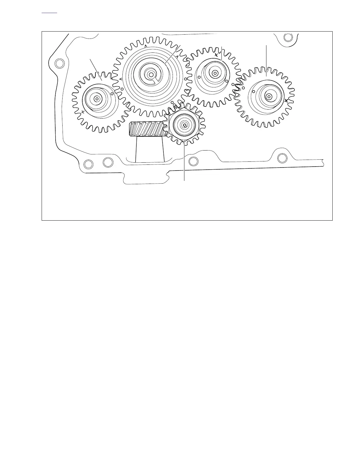
Figure 3-64. Cam and Pinion Gear Timing Mark Indexing
X= Color Code location on gear face
1. Rear Exhaust Cam Gear (15-1)
2. Rear Intake Cam Gear (15-2)
3. Front Intake Cam Gear (15-3)
4. Front Exhaust Cam Gear (15-4)
5. Pinion Gear
1
2
3
4
5
b0806x3x
NOTE
Though not depicted, Rear Intake Cam
Gear has 46 teeth and Pinion Gear has 23
teeth.
 Loading...


