3-44 2002 Buell X1: Engine
HOME
REMOVAL/DISASSEMBLY
1. See Figure 3-62. Thoroughly clean area around gear-
case cover (17) and lifters. Blow loose dirt from crank-
case with compressed air.
2. Remove any parts that will interfere with gearcase disas-
sembly (i.e., exhaust header, air cleaner, etc.).
3. Remove push rods. See 3.5 CYLINDER HEAD.
4. Remove hydraulic lifters. See 3.15 HYDRAULIC LIFT-
ERS.
5. Check for minimum cam gear end play. Record readings.
6. Remove cam position sensor and rotor from gearcase
cover. See 4.30 CAM POSITION SENSOR AND
ROTOR.
7. Place a pan under gearcase to collect oil. Remove cover
screws. Carefully remove gearcase cover. Discard old
gasket (9).
NOTE
If cover does not come loose on removal of screws, tap lightly
with a plastic hammer. Never pry cover off.
8. Remove cam gears (1, 2, 3 and 4). Carefully mark each
component to ensure correct installation.
NOTE
Nut (11) is secured by LOCTITE THREADLOCKER 262 (red)
on the nut threads.
9. Remove nut (11). Slide pinion gear (5) and oil pump
drive gear (12) off pinion shaft.
CLEANING AND INSPECTION
1. Thoroughly clean gearcase compartment, gearcase
cover and gears in solvent to remove oil and carbon
deposits.
2. Blow out all cover oil passages and bushings with com-
pressed air.
3. Clean old gasket material from gearcase and cover faces
with cleaning solvent.
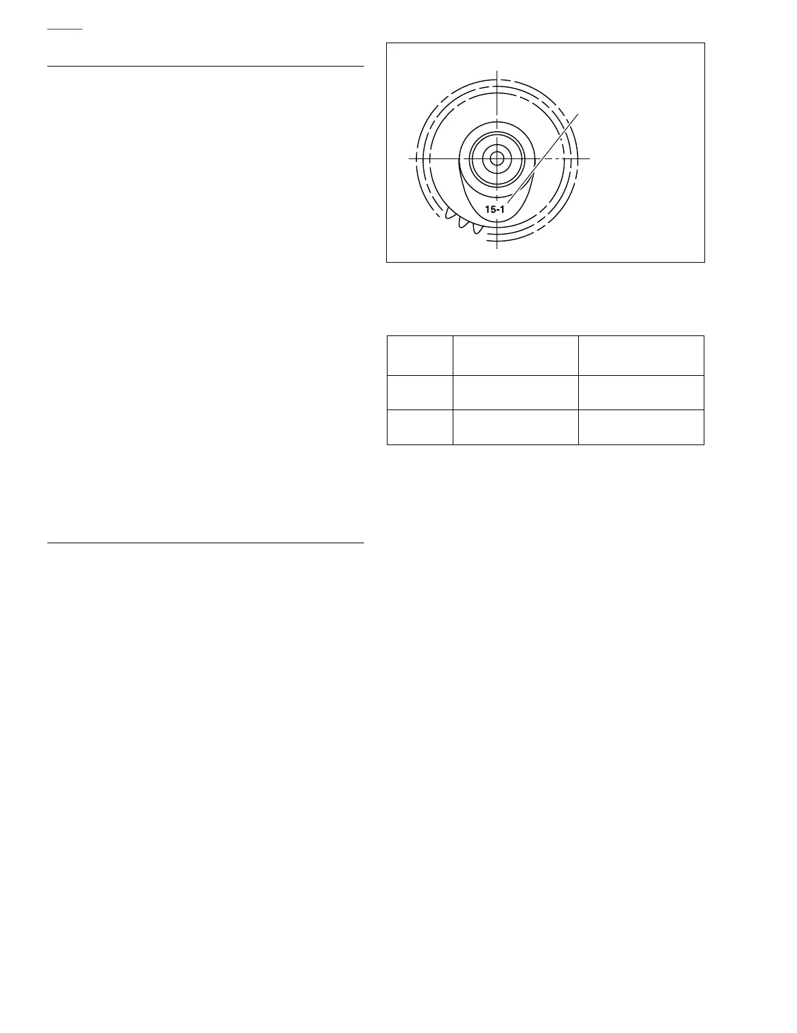
Cam and Pinion Gear Identification
See Figure 3-63. Cam lobes are stamped with the number
“15” followed by a number (1, 2, 3 or 4). The number “15” indi-
cates model year application; the number identifies the cam
location/function.
NOTE
Prior to changing any cam gears, check gear shaft fit within cor-
responding bushings. Worn bushings can cause excessive
backlash.
Cam Bushing Inspection and Removal
1. See Figure 3-62. Bushings (7, 8, 13, 14, 15 and 16) are
press fit in gearcase cover (17) and crankcase. Inspect
each bushing against its corresponding cam gear shaft
or pinion gear shaft. See Ta bl e 3-10.
2. See Figure 3-65. Use a BUSHING AND BEARING
PULLER (Part No. HD-95760-69A) to remove bushings
from gearcase cover and crankcase.
Figure 3-63. Cam Identification
Table 3-10. Gear Shaft Specifications
GEAR
SHAFT
CORRECT
CLEARANCE
SERVICE WEAR
LIMIT
Cam
0.0007-0.0022 in.
(0.0178-0.0559 mm)
0.003 in.
(0.076 mm)
Pinion
0.0023-0.0043 in.
(0.0584-0.1092 mm)
0.0050 in.
(0.1270 mm)
Identify cams by
stamped number
b0096a3x