3-56 2002 Buell X1: Engine
HOME
Pinion Bearing Selection
Select bearings using the identification information given for
inner and outer races and bearings. See Ta ble 3-12. and
Ta bl e 3-13.
NOTE
If either inner or outer race show wear, measure both races to
confirm correct bearing fit.
1. Use a dial bore gauge to measure and record ID of outer
race. Take four measurements on ID where bearing roll-
ers ride.
a. If the largest measurement is larger than 1.5672 in.
(39.8069 mm) or the required lapping to remove
wear marks would enlarge bore beyond 1.5672 in.,
continue at Step 5.
b. If largest measurement is 1.5672 in. (39.8069 mm)
or less, cover the cam bearings with masking tape to
prevent debris from entering bearings. Assemble
crankcase halves.
NOTE
The next step requires lapping the outer race. To keep
sprocket shaft and pinion shaft bearings aligned the lap must
be supported by an adaptor or pilot in the left crankcase half.
2. See LAPPING ENGINE MAIN BEARING RACES. Lap
race until all wear marks are removed.
3. Measure and record ID of race at four places.
4. Check measurements against these specifications:
Largest ID measured: 1.5672 in. (39.8069 mm) or less
Roundness of ID: within 0.0002 in. (0.0051 mm)
Taper: within 0.0002 in. (0.0051)
a. If lapping increased bore ID to larger than 1.5672 in.
(39.8069 mm), go to Step 5.
b. If roundness or taper do not meet specifications,
continue lapping until specifications are met.
c. If all specifications are met, continue at Step 7 to
remove and size inner race.
5. Press the outer race from the right crankcase. Press
new outer race into crankcase flush with inside edge of
cast-in insert.
See Figure 3-89. Dimensions are shown for fabrication of
tools used in pressing the outer race into or out of crank-
case.
6. The new outer race must be lapped slightly to true and
align with left case bearing and to meet the following
specifications. See LAPPING ENGINE MAIN BEARING
RACES.
ID: 1.5646 - 1.5652 in. (39.7408 - 39.7561 mm)
Roundness: within 0.0002 in. (0.0051 mm)
Taper: within 0.0002 in. (0.0051 mm)
Surface finish: 16 RMS
7. See Figure 3-86. Pull inner race from pinion shaft using
TWO CLAW PULLER (Part No. HD-97292-61), CENTER
CAP (Part No. HD-95652-43A), and BEARING SEPARA-
TOR (SNAP-ON TOOLS Stock No. CJ950). Apply heat
to race to aid removal.
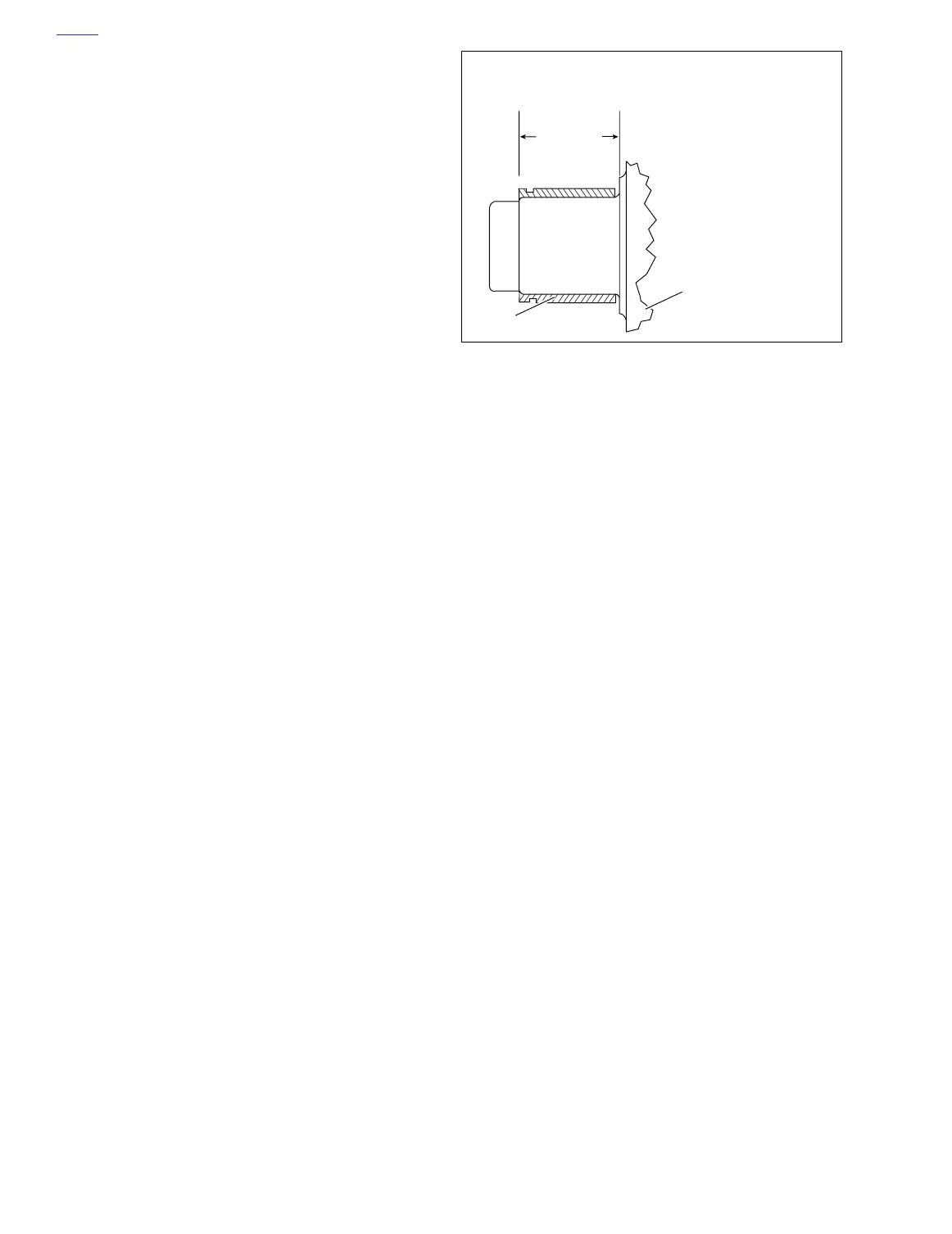
8. See Figure 3-88. Press new inner race on pinion shaft
as shown. The new inner race must be ground by a com-
petent machinist to OD dimension range for the finished
lapped ID of the outer race. See Ta ble 3-13. The finished
inner race must meet these specifications. For neces-
sary dimensions for constructing a press-on tool see Fig-
ure 3-89. When the tool bottoms against the flywheel,
correct inner race location is automatically established.
Roundness: within 0.0002 in. (0.0051 mm)
Taper: within 0.0002 in. (0.0051 mm)
Surface finish: 16 RMS
NOTE
Always use the smallest outer race ID measurement and the
largest OD inner race measurement when selecting bearings.
9. The following example illustrates how to determine the
required inner race OD.
a. See Ta ble 3-13. For example purposes, suppose the
smallest outer race ID measurement is 1.5651 in.
(39.754 mm). This requires an inner race OD range
of 1.2496-1.2504 in. (31.740 - 31.760 mm).
NOTE
Have machinist grind outer race to center or middle of
required OD range. This will prevent grinding outer race
undersize and gives a more easily achieved tolerance range.
b. Grind inner race. Measure OD at four places. Check
that specifications in Step 8 are met.
c. For example purposes, suppose the largest inner
race OD measurement after grinding is 1.2499 in.
(31.747 mm) OD.
d. With a 1.5651 in. (39.754 mm) ID outer race and a
1.2499 in. (31.747 mm) OD inner race, a blue bear-
ing is required.
Figure 3-88. Inner Race Location
1.145 in. (29.083 mm)-
1.135 in. (28.829 mm)
1. Pinion Shaft
Inner Race
2. Flywheel
(gear side)
b0165x3x
1
2