6
JDF-2S or JDF-4S DOOR COVER INSTALLATION
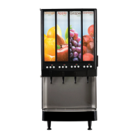
Step 1: Familiarize yourself with the circuit board switch
membrane connector layout before connecting the
switch membranes to the appropriate stations.
Chilled Water: Optional feature on JDF-4S models.
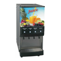
Step 3: After connecting all switch membranes to the
circuit board, place door cover over the inner door as-
sembly.
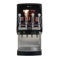
Step 5:
Finish screwing all screws down until they are
set in position (Do Not Over Tighten).
Step 6: Place flavor labels into label holders accord
-
ingly to the product being placed in the cabinet per
dispense station.
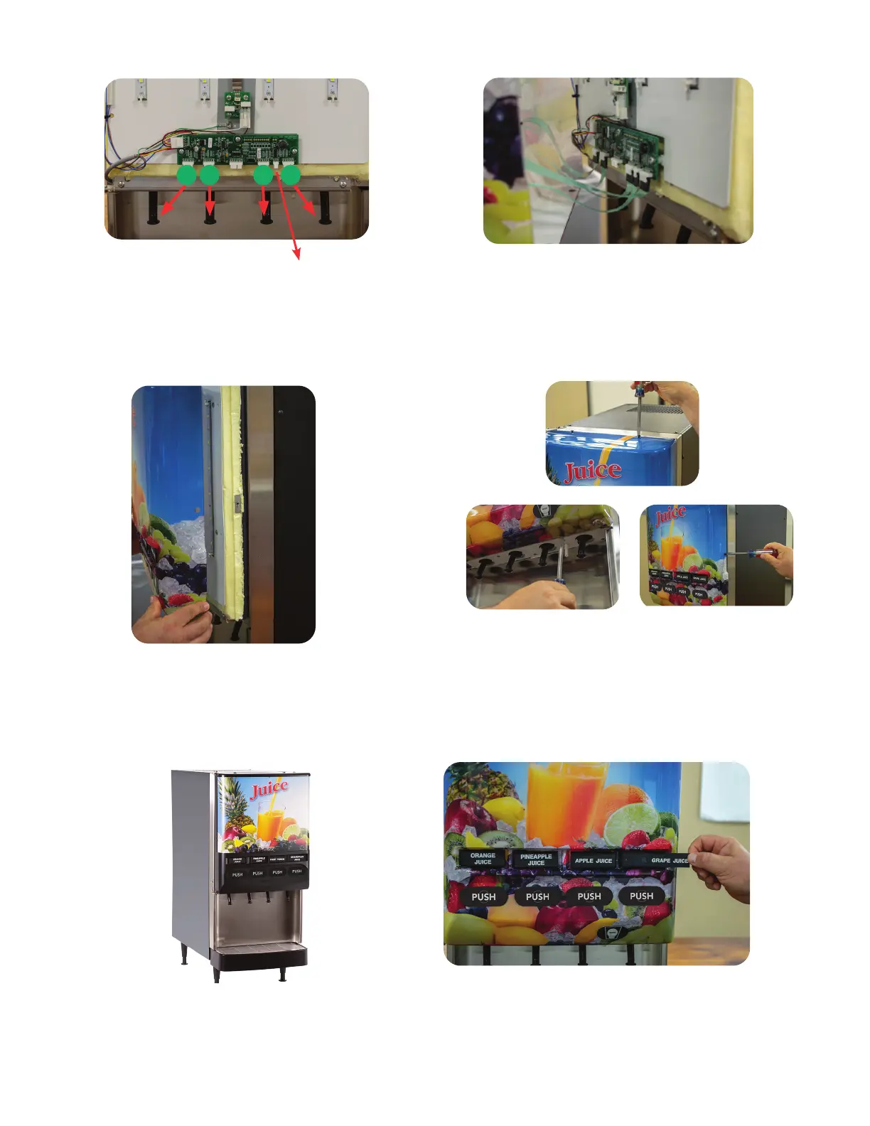
Step 2: Hold door cover close enough to inner door
and connect all switch membranes to the circuit
board before door placement onto the inner door
assembly. Model JDF-2S: Switch membranes con-
nect onto circuit board connectors 1 (J2) & 2 (J3).
Step 4: Locate the 5 provided screws. Install and
start all 5 screws through the door cover holes and
into the receiving threaded weld nut (2 upper, 2
lower and 1 right side).
Station Station Station Station
1 2 3 water 4
2 3 41
Upper
Lower Side