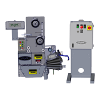
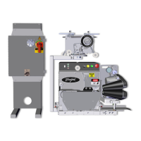
The Burford Model 8830 Applicator (Station 2) is a service manual for a device designed to apply a controlled amount of garlic oil, soy oil, or butter onto product without interruption to the pan flow. This document provides comprehensive information on installation, operation, and maintenance procedures.
Technical Specifications
The applicator requires the following utilities:
- Air: 1 scfm @ 60 psi
- Electricity: 208/220-50/60-1 phase @ 30 amps
Function Description
The Burford Model 8830 Applicator operates by starting a conveyor, placing a pan on it, and allowing it to travel toward the spray rail assembly. A pan sensor detects the leading edge of the pan and sends a signal to the PLC to activate the applicator nozzles, applying the selected liquid to each pan as it passes.
The system includes:
- Control Panel: The main interface for operating and monitoring the machine.
- Melting Racks: Used for melting solid products like butter.
- Product Pump: Responsible for delivering the liquid product.
- Ethernet Connections: For communication within the system.
The control panel features a Light Tower (indicates machine status), Primary Disconnect (removes electrical power), Main Display (interactive screen for menu, errors, and settings), and a Start/Stop Button (removes electrical power from components).
The main screen functions include:
- OFF: Turns off all internal relays and clears programming registers.
- PREHEAT: Turns on the melting rack and product tank water jacket circulating pumps and initiates temperature controls. The agitator is also turned "ON" after a 15-second delay. The product pump and spray nozzle trigger sensor are not energized.
- CIRCULATE: Melting rack, product tank water jacket, agitator, and butter pump are turned "ON". Spray nozzle trigger sensor is not energized. Product pump will be at low speed for 10 seconds, then switch to normal run speed once proper operating pressure is verified.
- RUN: Same as "CIRCULATE," except the trigger sensor activates spray.
- LOGIN / LOGOUT: Allows authorized users to enter their user name and password and access the "MANUAL EDIT MODE." LOGOUT returns the unit to "AUTO MODE."
- MANUAL EDIT MODE: Password protected, allows authorized users to create recipes and make additional machine setting changes.
- Other Functions: Touch "ICON" to access additional pop-up screens. "MANUAL EDIT MODE" is password protected.
Usage Features
Initial Start-Up:
- Turn on the electrical power via the main enclosure disconnect switch.
- Verify the red "START/STOP" button is in the out position.
- Initiate machine operation by closing the appropriate isolation valve(s) and checking all hoses are securely connected.
- The following screen will be shown on the operator display.
- Once the unit has completed the set-up sequence, the "MAIN MENU" screen will be displayed. Verify the correct recipe is displayed. If not, touch the "RECIPE SELECT" button and highlight the desired recipe, then press "enter".
- Touch "PREHEAT" to access this function. Adjust the melting rack and product tank heater controls to begin preparing butter for production. Verify the agitator is free from any obstruction and the backpressure regulator adjustment screw is backed out to minimize pressure.
- After butter has been melted and of desired consistency inside the product tank, open the appropriate isolation valve(s) and verify butter has completely filled infeed hose. Touch "CIRCULATE" and allow the butter to completely fill the system and circulate for 10 minutes. Verify spray nozzle operation by touching the "SPRAY RAIL #1" icon and use the "PURGE" or "SPRAY" buttons. Adjust the backpressure regulator to give the desired output quantity.
- Switch to the "RUN" function once satisfied with machine operation.
- Begin production operations.
Creating a New Recipe:
- Initially, the unit will be in "AUTO" mode. Touch "LOGIN" and enter the authorized user name and password.
- Once logged in, touch the "MANUAL EDIT MODE" box.
- Once in "MANUAL" mode, the user has access to the machine "SETPOINTS" (upper left corner) and "EDIT RECIPE NAME" (upper left corner).
- To change the recipe name, touch the "EDIT RECIPE NAME" box and follow screen directions.
- To exit the "MANUAL" mode, touch the "RETURN TO AUTO MODE" box. Then touch the "LOGOUT" box to prevent unauthorized access.
Changing Spray Time & Purging:
- From the "MAIN MENU" screen, touch the "SPRAY RAIL #1" icon.
- This pop-up is accessible from either "manual" or "auto" modes. Touch "PURGE" to activate all active nozzles for the entire time the "PURGE" is touched. Touch "SPRAY" to activate all active nozzles for (1) spray cycle. Touch the "SPRAY RAIL SPRAY TIMES" box to advance to the screen shown below. Touch individual nozzle icons to toggle nozzles valves "ON" or "OFF".
- Touch the desired "ROW" to change the spray time (in milliseconds) for the selected "ROW". Select "Delay to Spray" to enter amount of time (in milliseconds) for all active "ROWS" to be delayed once the pan sensor has been activated.
Changing Machine Setpoints:
Nine screens are related to machine set-up, accessible only in "MANUAL" mode via the "MAIN" screen "SETPOINTS" button. All changes made will only be saved to the recipe name shown in the upper left corner.
- Fill Level Setpoints: Sets the tank level (in percent) at which the valve responsible for filling the tank will close, and the tank level (in percent) at which the valve responsible for filling the tank will open. Range: 0 – 100.
- Thermocouple Calibration Offsets: Adjusts offsets to correct differences between thermocouple output and actual temperatures. Range: -999 to +999.
- Pump Setup: Sets pump speed (0-75 Hz), low pressure run (determines pressure that must be reached while pump is in "low" speed mode), high pressure shutoff (determines pressure that if reached during "high" speed mode will cause the unit to shutdown).
- Melt Rack Alarm Setpoints: Determines the maximum desired temperature for the melt rack(s).
- Rail Override: When "enabled," the rail number displayed in the box below "set rail" overrides all other spray rails. Useful in the event of rail recognition sensor failure.
- Mix Tank Alarm Setpoints: Determines the maximum and minimum desired temperature for the mix tank.
- Tank Level Sensor Calibration: Used to fine-tune the sensitivity of the level sensor.
- Goto Display Configuration Screen: These settings are preset at the factory.
- Encoder Setup: Used during initial machine installation or encoder replacement.
Settings and Adjustments:
- Nozzle Height: The height of nozzles determines the amount of product coverage. Taller nozzles result in a smaller coverage area and reduced overspray. Turn the control knob to raise or lower the nozzle height.
- Product Sensor: The sensor is set to activate the nozzles once the pan has reached the proper position. The sensor can be adjusted by loosening the mounting bolts and sliding the sensor holder up or down.
- Product Flow Rate: Influenced by dispensing rate, product temperature, actuation time, pump speed, and backpressure. The first variable, product temperature, is discussed in section 4.4. The second variable, actuation time, determines the amount of time in milliseconds the spray valves are actually dispensing product. The third variable, pump speed, controls the rate of flow the pump is capable of discharging. The remaining variable, backpressure, is indicated by the gauge located at the infeed of the manifold. The valve works by adjusting the knob to limit the flow and increase backpressure.
- Product Tank Level Sensor: The ultrasonic tank level sensor is pre-programmed with correct operational settings. The sensor's internal settings will work with any of the 8830 units. To maintain interchangeability, these settings should not be modified. This sensor has an analog output and is used to determine fill levels, as well as, alarm setpoint violations. The agitator is prevented from running when the tank lid is removed.
Maintenance Features
Filling the Product Tank Water Jacket:
- Verify all electrical power is removed from the unit.
- Connect the house water supply to the yellow water valve located at the side of the product tank.
- Turn on the house water supply, and then open the yellow water valve on the product tank.
- Close the yellow water valve when the water level reaches the sight tube. Turn on "PREHEAT" from the operator panel. This will operate the circulating pump. Add or remove water until the sight tube is half full while the circulating pump is running. The water jacket must be completely filled; otherwise, the heater will not vent properly during machine operation.
- Turn off the house water supply; disconnect the supply hose from the yellow water valve.
- Check the sight tube daily for correct water level. Additional water may be required due to evaporation.
- Filling the water jacket too rapidly may result in water expulsion from the vent.
Filling the Melting Rack Water Jacket:
- Verify all electrical power is removed from the unit.
- Disconnect the supply hose and connect the provided quick connect coupling to the melting rack discharge hose inlet.
- Connect the house water supply to the coupling.
- Slowly fill the melting rack water jacket until water is seen in the sight tube. Water level should be maintained between lines as shown on the right. Turn off the water supply and disconnect from the discharge inlet.
- Reconnect the discharge hose to the melting rack.
- Filling the water jacket too rapidly will cause water spillage from the vent.
- Touch "PREHEAT" from the operator control panel and verify the water level through the sight tube.
- Verify the sight tube level, repeat the procedure until proper water level is maintained.
- Low water level inside the water jacket may result in heater failure.
Restoring Product Flow:
If the "CIRCULATE" is inadvertently turned off or the unit loses power for an extended period, the viscosity of the product inside the tank may become too high to adequately flow through the system.
- Turn on the unit and select "PREHEAT".
- Shut the isolation valve located on the front of the product tank.
- Disconnect the inlet hose from the valve to the pump and manually flush butter from the line. It may also be necessary to remove and clean the elbow and tee on the infeed side of the pump. Reconnect the hose and fittings.
- Turn on the "Tank Control" and adjust the setpoint to 96° F. Allow the product tank to heat to the pre-set temperature.
- Open the isolation valve and verify the preheated butter has reached the pump infeed.
- Select "CIRCULATE" from the control panel. Check for fluid circulating through the fluid lines and returning to the product tank.
- System must be depressurized before disconnecting hoses.
- Allow product temperature to stabilize, test application consistency (purge nozzles), and then resume operation.
- If the high pressure switch is made, the pump may cycle between low and high speeds, trying to break the viscous fluid up and restore flow.
Changing the Product Filter:
- Position a suitable catch pan beneath the discharge side of the pump and open the isolation valve to drain product from the filter. Once the filter has drained, remove the product feed hose from the filter discharge.
- Loosen the endbell clamp on the filter assembly. There is a spring inside the assembly so be prepared for the internal components to "spring" out once the clamp is removed.
- Use care not to damage the o-ring when sliding the filter unit out of the housing.
- This filter screen is shown without the available filter sleeve. If used, remove and replace the filter sleeve with a new sleeve once the filter screen is properly cleaned and checked. To install the sleeve: Remove both endcaps from the screen and slide the sleeve over the screen. Once centered, push the sleeve inside the screen ends on both sides and replace the endcaps to secure.
- Position the spring cap on the end of the filter screen and carefully slide the filter screen into the housing. This may take more than one attempt to allow the spring cap to properly seat on both the filter screen and the spring inside the housing assembly.
- Position the endbell o-ring into position and compress the spring to allow the endbell clamp to be reassembled.
- Connect the product hose.
- Procedure complete.
Product Pump Seal Maintenance:
- Remove and discard pump body o-rings, using an o-ring removal tool furnished with the product pump.
- Remove shaft sleeves and shaft o-rings.
- Thoroughly clean and inspect o-ring grooves, shafts, and sleeves. Do not re-use sleeves that are grooved or scratched.
- Apply an approved o-ring lubricant to new o-rings and insert them into pump body grooves and shaft grooves. Shaft o-rings should be installed into the front shaft groove (closest to shaft spline). Sleeves may be either slotted or have prongs.
- Assemble shaft sleeves against the shaft shoulder, being sure the sleeve prongs do not line up with the drive pin on the shaft. However, do place the slotted sleeve over the pin if you have that type of sleeve.
Cleaning Procedures:
Basic Procedure (after each production run):
- Verify "Sanitation" is displayed in the recipe name.
- Disconnect the return line from the front of the use tank and place it in a suitable catch container. Pump remaining butter into a suitable container.
- Partially fill the product tank with hot water; turn on the agitator. Flush through the system using the "Purge" button. Wipe residual butter from the inside of the product tank walls and repeat as necessary until product has been flushed from the system.
- Once the majority of the butter has been flushed into a container, reconnect the return line and circulate hot water through the system until product has been flushed from the supply and return hoses.
- Purge nozzles.
- Empty water from the system.
- Repeat steps 3 and 4 using a hot water solution with a sanitizing agent such as Ball® mfg. Quad10®, then flush with clean water.
- This procedure will remove most, but not all of, the butter inside the product tank and lines. Complete disassembly of the unit, as shown in the following sections, is required to completely clean the system.
- Do not run the product gear pump dry or damage will occur.
Cleaning the Manifold Assembly:
- Complete steps outlined in "Basic Procedure".
- Verify the product tank is empty and power sources are secured according to plant lockout/tagout procedures.
- Position a suitable catch pan beneath the isolation valve (arrow) and open to drain.
- Disassemble plumbing at all connection fittings to ensure effective cleaning of SST piping, pressure hoses, and filter.
- Close isolation valve(s) and back pressure valve on the manifold to prevent product leakage when moving the unit to the C.O.P. room for cleaning. Disconnect spray gun product hoses at their respective disconnect fittings.
- Disassemble manifold fittings as necessary to ensure effective cleaning of spray gun hoses and manifold tubing. Manifolds are attached to frame assembly with wingnuts to facilitate removal of the entire manifold for cleaning.
- Once all components are disassembled, clean interior of all product lines, sanitary fittings and manifolds with a sanitizing solution and/or by pressure washing. C.O.P. tanks are recommended to thoroughly clean pipes, fittings and tubing (where applicable).
- Assemble (see reference photo, next page) and resume operation.
- Do not submerge spray guns in C.O.P. Tank. Flush with appropriate solution to clean.
Cleaning the Product Tank, Agitator and Melting Rack:
- Loosen and remove wing nuts, then disconnect control cables from the melting rack thermocouple and heater. Disconnect water supply and return hoses from the melting rack (both sides). Remove melting rack covers.
- With assistance, lift the melting rack from the product tank.
- Remove the agitator cap.
- Loosen the agitator setscrews on both sides of the agitator shaft (if agitator removal is necessary).
- Carefully lift the agitator from the tank. Wipers are spring-loaded, use care as they exit the product tank.
- Clean any remaining product from the tank, agitator assembly, and melting rack. Rinse with clean water.
- Assemble in reverse order.
Cleaning the Product Pump:
- Before beginning this procedure, verify the product tank and infeed tubing have been drained in accordance with section 10.2.
- Begin by disconnecting all infeed and discharge tubing from the actual pump assembly. The gasket (P/N 611354) at the infeed of the pump contains a screen for preventing large objects from entering the pump. Very important that this gasket be used during reassembly.
- Use care when disconnecting the pressure switch.
- Loosen and remove wing nuts. May require a soft hammer to loosen wing nuts.
- Remove cover, if it is stuck, loosen with a soft hammer. Remove and discard cover O-ring.
- Remove rotor retaining nuts. Use the special wrench supplied with the pump and hit it sharply with a soft hammer to loosen the nut.
- Orient rotors perpendicular to each other and remove the rotor with both wings exposed first. Handle rotors with care to avoid knicks and scratches. If it is stuck tight, use a gear puller or hardwood lever behind the rotor hub to force it off the spline.
- Remove the pump body by pulling it straight off the studs. Use a soft hammer to assist if the body is stuck tight.
- Clean and inspect the pump body and rotors thoroughly.
- Once components are clean, begin re-assembly by sliding the pump body over the drive shafts and mounting studs. Be careful, seal components are not knicked or knocked out of place. Press the body firmly against the gear case, engaging dowels.
- Assemble a rotor onto the shaft, engaging the large spline tooth with the large groove in the rotor. Rotate the shaft until the rotor wings are on a vertical centerline. Install the second rotor and secure both rotor retaining nuts (clockwise). Tighten the nuts to 30 foot-pounds.
- Install the O-ring in the cover groove.
- Mount the cover on the studs and push it against the pump body, being sure the O-ring remains in the groove.
- Attach wing nuts (clockwise) and tighten by hitting them sharply with a soft hammer.
- Lightly coat all O-rings with a food grade lubricant (grease) upon reassembly.
Preventive Maintenance:
- Flush the tank and butter nozzles after each production run with hot water.
- Remove and clean nozzle tips weekly.
- Check sight tubes daily for correct water level.
- Visually inspect air and product lines. Replace when needed.
- Break apart and clean the product pump as needed.
- Visually inspect vacuum assembly filters. Replace when needed.