Do you have a question about the Burford 2000 and is the answer not in the manual?
Provides essential safety procedures for operating and maintaining the Servo Tyer.
Legal disclaimer regarding product liability, specifications, and design changes.
Details electrical requirements and air pressure for the Servo Tyer.
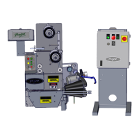
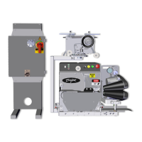
Differentiates between Model 2000 and 2100 based on product flow direction.
Specifies operating speeds, power, and conveyor spacing for optimal performance.
Provides formula and guidance for determining correct bag neck length.
Identifies key components of the Servo Tyer unit with labels.
Shows the physical locations of Emergency Stops and Main Disconnect.
Describes the main mechanical and electrical components for the tying function.
Details the buttons, lights, and switch on the tyer's control interface.
Explains the function of the needle in wrapping and placing ribbon.
Describes how the twister hook twists and ties the ribbon.
Explains the dual function of shearing and holding the ribbon.
Details how the bag switch is actuated to start the closure process.
Explains its role in measuring dispensed ribbon length.
Describes its function in adjusting the tie window.
Explains their role in transporting the bag neck.
Details how the operator adjusts gathering belt speed.
Describes components housed within the main electrical enclosure.
Explains its function in controlling power to the unit.
Details components managing ribbon tension and spool holding.
Explains its use in adjusting brake tension for ribbon dispense.
Describes its function in holding or releasing ribbon rotation.
Explains its role in decreasing ribbon tension by releasing brake pressure.
Describes how it detects if ribbon is no longer threaded.
Explains its function in flattening and straightening the bag neck.
Details how it varies gathering brush tension.
Describes its function in metering airflow for bag tail flattening.
Explains its role in restraining the bag neck during the tie process.
Lists optional upgrades available for the Servo Tyer.
Explains its function in monitoring packages and stopping the bagger.
Describes its ability to automatically adjust gathering belt speed.
Explains how it shows machine status and error messages.
Describes its optional function of blowing the bag tail down.
Mentions available stand options for portability and adjustability.
Describes the optional conveyor for transferring products.
Provides step-by-step instructions for mounting the Servo Tyer.
Guides on wiring connections to bagger or conveyor systems.
Details the safety interlock circuit for tyer readiness.
Explains the signal indicating bagger status to the Servo Tyer.
Describes the relay for external counter integration.
Information on hiring trained technicians for installation.
Explains the overall principles of the Servo Tyer's tying cycle.
Identifies and describes functions of buttons, lights, and switches on the control panel.
Outlines the normal procedure for starting the Servo Tyer daily.
Guides on adjusting the bag switch for proper package activation.
Details how to adjust the force and tension of the holder shear.
Provides steps for aligning the shuttle bar for free movement.
Explains how to set tension for gathering belts to avoid motor load.
Guides on setting gathering belt speed for proper product transfer.
Explains how to adjust belt guide spring tension based on speed.
Describes the proper alignment of gathering belt teeth.
Details the proper gap setting for all five proximity sensors.
Explains how to vary brush tension using the adjustment knob.
Describes how to adjust airflow for the gathering brush.
Guides on checking and adjusting spool rotation for free movement.
Provides instructions for changing needle assembly rollers.
Details the proper gap setting for the twister hook and holder shear.
Explains how to adjust tie tightness using ribbon guide and belt pulley.
Describes parameter configuration using DIP switches on the auxiliary board.
Details parameter configuration using DIP switches on the CPU board.
Lists fuses and circuit breakers in the main enclosure and boards.
Provides instructions for upgrading or replacing PROMs on the CPU board.
Explains communication via a terminal over the serial port.
Guides on PC communication for status monitoring and troubleshooting.
Details the use and configuration of Burford's terminal program.
Guides on configuring Windows Terminal for Servo Tyer communication.
Identifies the necessary cable for PC connection.
Discusses commands for status output and troubleshooting.
Explains the initial information output upon power supply.
Details commands for checking and setting the unit's time and date.
Explains how to display and review the machine's operational history.
Describes how to display servo motor position and speed data.
Explains how to display the reason for the most recent controller reset.
Details how to enable debug mode for monitoring bag switch activity.
Explains how to initiate the Servo Tyer's homing sequence.
Describes how the controller counts ribbon dispensed and checks for heels.
General advice and notes for troubleshooting the Servo Tyer.
Explains the function of LEDs on the Field Termination Board for diagnostics.
Lists and explains error codes displayed on the CPU board's LED.
Describes the meaning of different alarm beeps and their codes.
Introduces flow charts for diagnosing and repairing specific issues.
Provides instructions for lubricating key bearings for proper operation.
Outlines daily, weekly, monthly, and quarterly maintenance tasks.
Step-by-step guide for replacing the fuse on the power supply board.
Lists expected DC voltages for various components.
Describes how to check encoder operation using LEDs on the FTB.
Guides on testing motor leads for continuity and connection integrity.
Explains how to test the fuses for the servo motors.
Details how to measure the 36V DC power supply output.
Guides on checking proximity sensor operation via LEDs.
Details how to test the 5V and 12V DC power supplies.
Explains how to test the BCD switch for controlling belt speed.
Guides on checking the bag switch operation using its LED.
Provides steps for testing relays on the Field Termination Board.
A quiz to assess operator understanding of basic functions.
A quiz to assess understanding of mechanical aspects and error codes.
Lists essential spare parts to keep in stock for minimal downtime.
Provides an overview diagram of the tyer's main components.
Shows a side view illustrating key components and their layout.
Illustrates the arrangement of motors, encoders, and pulleys.
Details the proximity sensor for the holder shear and its adjustment gap.
Illustrates the ribbon drop proximity sensor and its adjustment gap.
Shows the ribbon dispense proximity sensor and adjustment gap.
Details the proximity sensor for the needle's home position and adjustment.
Illustrates the proximity sensor for the twister hook home position.
Diagram identifying electrical components within the main enclosure.
Details the CPU, Auxiliary, and Field Termination boards.
Lists and describes the function of various relays on the boards.
Functional diagram showing the motor control system flow.
Schematic of the power and control circuit for the gathering brushes.
Schematic illustrating the DC power latching circuit.
Schematic of the bagger enable circuit and safety interlock.
| Brand | Burford |
|---|---|
| Model | 2000 |
| Category | Industrial Equipment |
| Language | English |