110
Chapter 7
Diagnostic LED's, cont’d
FTB - D14:
Indicates when the needle triggers the needle home proximity
FTB - D15:
BAGGER
Indicates when the bagger enable relay, CR4 on the FTB, is
energized.
FTB - D16:
Indicates when the dancer arm triggers the ribbon drop proximity
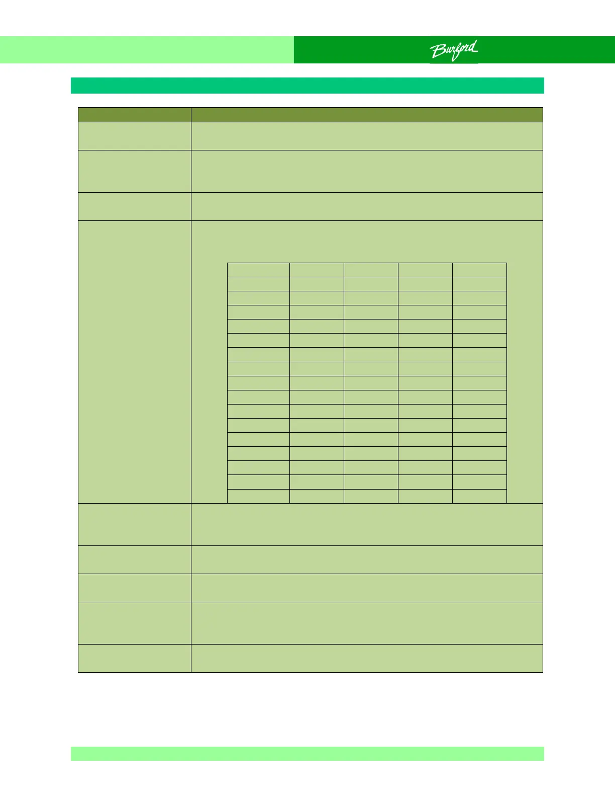
FTB - D18/BCD 8,
D20/BCD 4,
D22/BCD 2, and
D23/BCD 1:
Indicates the signals coming from the belt speed push wheel
switch. The following table shows how the LED's should respond
to each setting.
FTB - D19:
SERVO ENABLED
Indicates when the servos enabled relay, CR2 on the FTB, is
energized. Also, implies that CR1 on the main panel should be
energized and there should be power to the servo motors.
FTB - D24, D27:
Indicates CPU activity.
FTB - D25: HORN
Indicates when the horn relay, CR5 on the FTB, is energized.
FTB - D28:
BRUSH/BELT
Indicates when the brush/belt relay, CR3 on the FTB, is
energized.
FTB - D29, D31:
Indicates CPU activity.