44
Chapter 3
CHAPTER 3: INSTALLATION
Mechanical Installation
1. Locate the template drawing provided with your manual packet and review your
application. Refer to pg. 18 for the general location.
2. Center punch the three hole locations indicated. Drill the three 3/8" diameter mounting
holes required for the standard unit (clearance holes for 5/16" bolts).
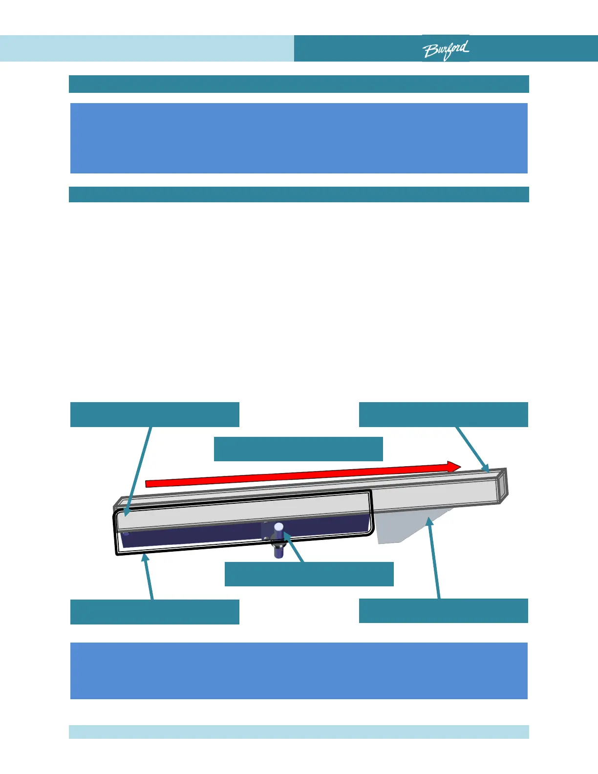
3. Locate the Servo Tyer/Brush pivot bracket and bolt this assembly onto the conveyor
as shown below with two (2) 5/16" bolts and nylon insert nuts provided. This post
should include a set collar for adjusting the height of the Servo Tyer. Square bracket
and tighten securely.
4. Locate the Servo Tyer location post, bolt to third hole, and secure loosely.
Drill Template
Conveyor Top
Tyer / Brush Pivot
Product Shelf
Tyer Location Post
Product Flow
These instructions are for a typical bagger. If your specific
installation requirements are different from what is described here.
Contact Burford
®
Corp. at (1-877-287-3673) or
The template drawing is intended for use with standard bread
packages. Depending upon your application, it may be necessary to
raise or lower all three holes. Layout the bolt pattern as described