88
Chapter 5
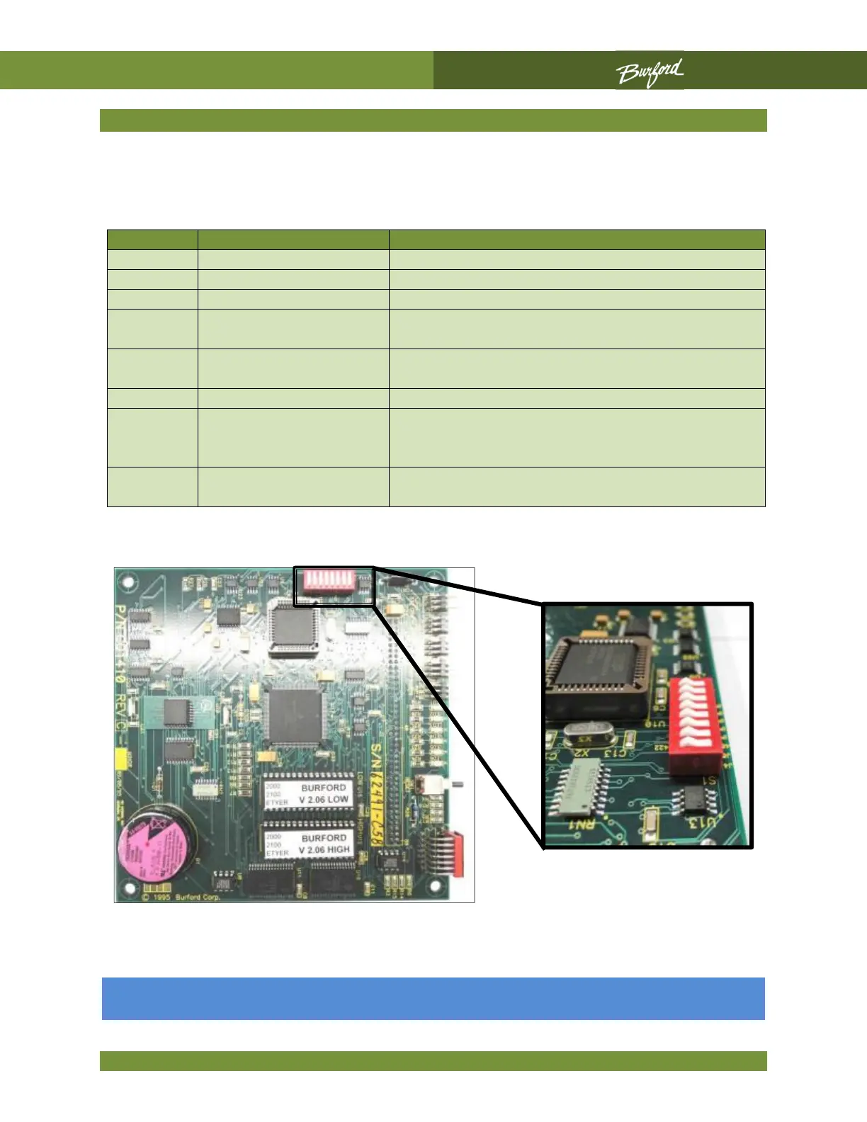
CPU DIP Switch Settings
The CPU board, P/N C01410, has a group of eight DIP switches labeled S1. The following
table identifies the switch functions.
4
INTERNAL H / S
EXTERNAL H /S CONTROL*
5
INTERNAL TWISTER
EXTERNAL TWISTER HOOK CONTROL*
7
PDS WILL NOT STOP
BAGGER (3 BEEP
NORMAL PDS (STOPS CONVEYOR)
8
COMMUNICATES
COMMUNICATES WITH OPTIONAL ERROR
All eight (8) DIP switches shown in the “OFF” position.