164
Chapter 9
CHAPTER 9: TEST PROCEDURES
Motor Encoders Test Procedure
An encoder can be checked for proper operation by following these steps.
1. Open the Main Enclosure.
2. Turn the disconnect switch ON.
3. Push the “ON” button located on the door to engage power.
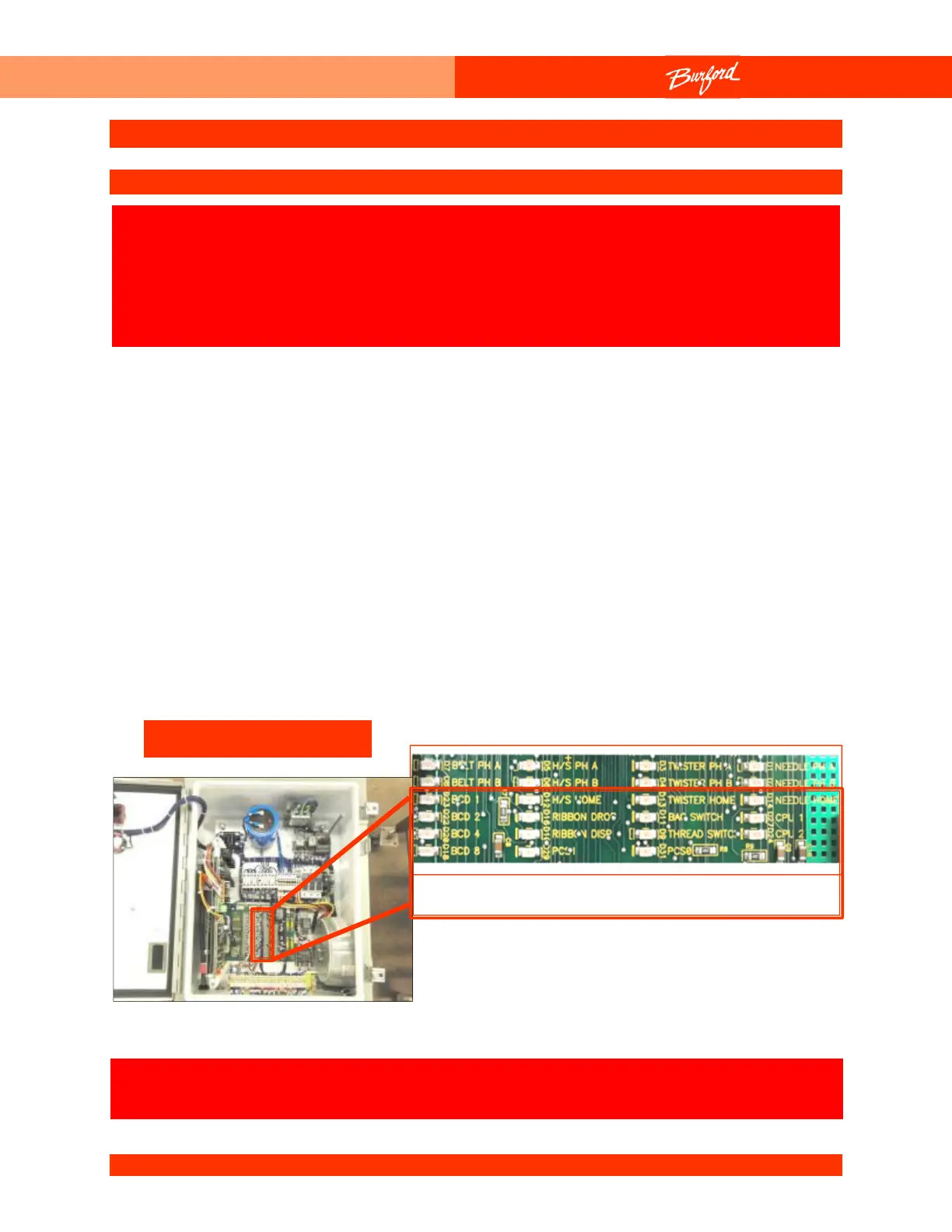
4. While turning the shaft of the motor very slowly, observe the Light Emitting Diodes
(LEDs) on the Field Termination Board. The eight (8) encoder LEDs are labeled
“BELT Phase A”, “BELT Phase B”, “H/S Phase A”, “H/S Phase B”, “NEEDLE Phase
A”, “NEEDLE Phase B”, “TWISTER Phase A”, and “TWISTER Phase B”. As you turn
a motor, its encoder LEDs should be turning on and off. Only one of the LED's should
toggle at any given time. However, the motor must be turned very slowly in order to
observe this sequence because each LED turns ON and OFF 500 times per motor
revolution.
If an encoder lead is broken or disconnected that LED will be ON all
SAFETY WARNING: The following procedure may require that tests
are made with the electrical enclosures open and power turned
“ON”. These tests should only be conducted by authorized
personnel who are aware of the electrical and mechanical hazards
present.