Operation 57
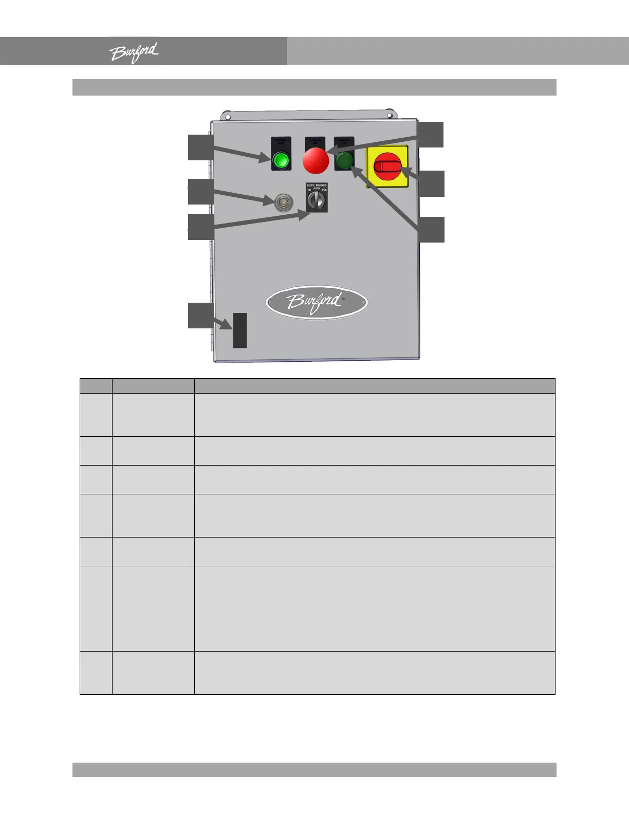
Main Enclosure
1 “On”
Pulls in the master control relay contacts and supplies power to
the Servo Tyer electronics. Does not supply power to the servo
2 “E-Stop”
Drops out the master control relay. Removes power from the
Servo Tyer electronics and the servo motors.
3 “Power On”
This lamp indicates that the master control relay contacts are
active and supplying power to the Servo Tyer electronics.
4
Main
Disconnect
Disconnects the AC power coming to the Servo Tyer controls.
This does not disconnect any interlock connections coming from
5
Audible
This gives the operator audible feedback as to the status of the
le alarm codes are described on pg.
6
“Brushes/Bel
ts Auto On”
This is a two position maintained selector switch. During normal
operation, it should be in the “AUTO” position. If the interlock
signal from the bagger is connected properly, the brushes and
belts will only run when the bagger is active. To override this
interlock signal and run the brushes and belts continuously, move
the switch to the “ON” position.
7
Seven
Segment
This device is used to display various codes that give the Servo
Tyers status (pg. 112).