116
Chapter 7
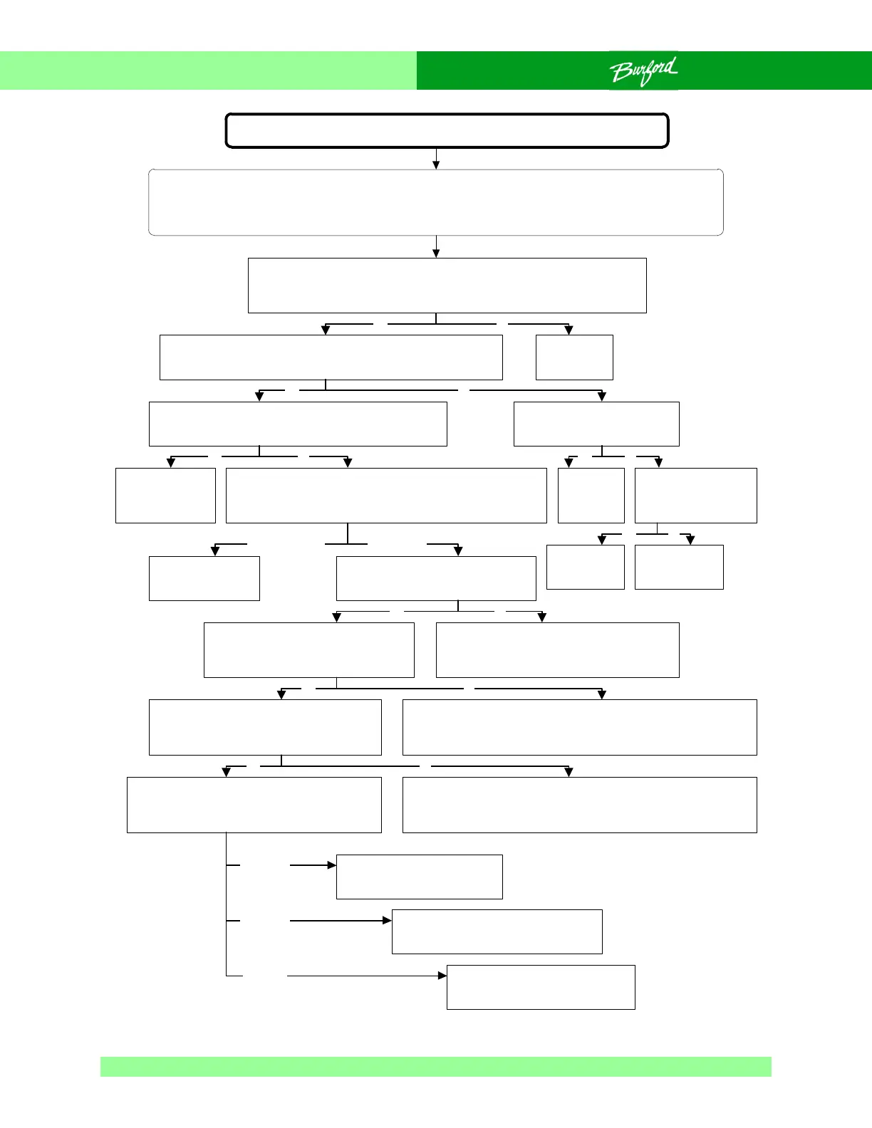
Flow Chart 0-1 Unit Will Not Power Up And Initialize
Unit will not power up and initialize
SAFETY WARNING:
The following troubleshooting procedure may require that tests be made with the electrical enclosures
open and power turned “ON”. These tests should only be conducted by authorized personnel who are
aware of the electrical and mechanical hazards present.
On the front of the main enclosure, turn “ON” the disconnect switch and
press the “ON” button. The power light should come “ON” and you
should hear the DC contactor energize. Does this work properly?
Check the seven segment LED on the CPU board which is
visible through the window of the main enclosure. Does it
display startup characters, then repeatedly display H004?
Go to Flow
Chart 4-1.
Press the “RUN” button on the control panel. Does the
tyer begin its homing sequence, then faults and the
CPU displays an error on the seven segment LED?
Is 5VDC and 12VDC power
getting to the AUX Board?
See Section 4.4.
Replace the
CPU board.
Is VAC power getting
to the input of the
Power Supply?
Replace the
Power
Supply.
Repair wiring to
Power Supply.
With the CPU board powered up,
check LED D6 beside relay CR9 on
the Aux Board. Is the LED “ON”?
The problem is with the DC power latch circuit, check
connections to the “RUN”, “STOP” and “HOOD” switches. See
Fig. 5-23 to troubleshoot, following 12VDC power from the
“HOOD” switch to the run relay CR1 on the Aux board.
Check that the servos enabled relay CR2 on the FTB is
properly seated in its socket. Watch the DC power
contactor CR1 in the main enclosure while pressing the
“RUN” button. Does the contactor engage?
Watch LED D1 beside relay CR1 on
the AUX board while pressing the
“RUN” button. Is the LED “ON”?
The problem may be on either the CPU or
AUX boards. Replace CPU board, retest. If
problem persists, replace the AUX board.
Test servos enabled relay, if relay
is good, check FU3 on FTB and
replace or replace FTB.
No power present to energize
contactor CR1. inspect wiring
to contactor CR1.
Yes
Yes
Yes No
No
Yes No
Yes No
No
Watch LED D19 beside the servos
enabled relay CR2 on the FTB. Push the
“RUN” button. Does the LED turn “ON”?
The connection between the AUX board relay and the FTB relay
is faulty. Check connection between boards (PIN 43), retest. If
issue persists, replace AUX board, retest. If issue persists
replace the FTB.
Place DC voltmeter across (J28) servos
enabled terminal on the FTB while pushing the
“RUN” button. Note the voltage reading before
and after the “RUN” button is pressed.
Normal reading, check wiring
to DC contactor. If OK,
replace DC contactor.
Never engages
Yes No
Check Aux board
relays, replace Aux
board as needed.
Only engages while
button pressed
NoYes
Yes No
~36V before
~ 0V after
~36V before
~36V after
~0V before