166
Chapter 9
Servo Motor Fuses Test Procedure
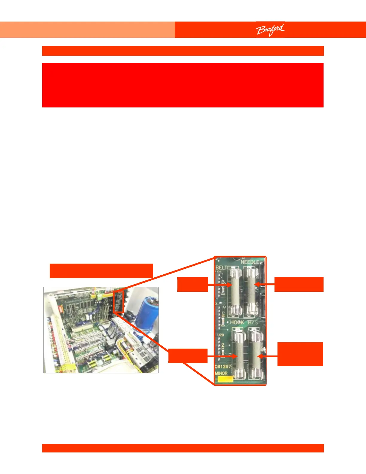
The fuses for the four (4) servo motors are located on the Auxiliary board. The motor
fuses can be checked by following these steps.
1. Turn the disconnect switch located on the Main Enclosure to “OFF”.
2. Locate the Auxiliary board on the electrical panel.
3. Remove the desired fuse from the Auxiliary board. The Auxiliary board is labeled for
fuse identification. This should be done carefully so as not to damage the traces
under the fuses. Never use a metal screwdriver.
4. With the fuse removed, check it with an ohmmeter. The resistance of any of these
fuses should be less than 1 ohm.
Holder
Hook
The following procedure may require that tests are made with the
electrical enclosures open and power turned “ON”. These tests
should only be conducted by authorized personnel who are aware
of the electrical and mechanical hazards present.