172
Chapter 9
Field Termination Board Relays Test Procedure
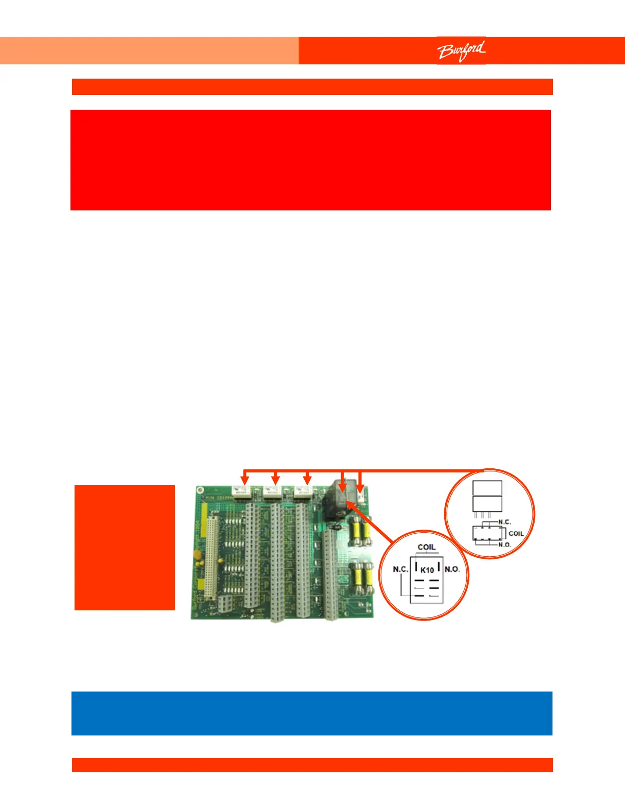
There are two different types of relays on the Field Termination Board. “CR2”, “CR4”,
“CR5”, and “CR6” are 12VDC relays and CR3 is a Potter & Brumfield K10P-11D15-12
(K10) relay. The K10 is a 12VDC relay. The relays can be tested by following these steps.
1. Turn the disconnect switch located on the Main Enclosure to “OFF”.
2. Remove the desired relay from the board (make note of the position in which it is
plugged in).
3. Use figure below to identify the pins for the coil of each relay. Check the coil of the
relay with an ohmmeter. The resistance of the dc relay coils should be about 925
Ohms. The resistance of the K10 relay coil should be about 4000 Ohms.
4. Check the resistance of the Normally Closed (NC) contacts. The resistance should
be less than 1 Ohm. Check the resistance of the Normally Open (NO) contacts.
The resistance should be infinite.
The following procedure may require that tests are made
with the electrical enclosures open and power turned “ON”.
These tests should only be conducted by authorized
personnel who are aware of the electrical and mechanical
Relays
A. Servos
enabled
B. Horn
C. Counter
D. Bagger
enable
All relays must be inserted correctly, note pin out on circuit board
silk screen.