4
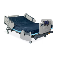
Burke Low Air Loss Support System
(Figure -1 Page 14):
The Burke Low Air Loss Support System is an alternating pressure & on-demand low air loss
system with width expansion side air bolsters, used to provide pressure reduction. It consists of a
control unit (A) which is used to inate a mattress replacement system (B) with width expansion side
air bolsters on each side. The control unit is designed to provide continuous static or alternating
pressure with low air loss relief at required patient comfort levels. The ABS/PVC blend enclosure
houses a medium output air pump (42~52 LPM), an alternating pressure solenoid valves, and a
micro-controller with pressure sensors, R.F auto fowler receiver, the micro controller controls all of
the above components, and provides desired patient comfort pressure and therapies.
The mattress replacement system (B) is comprised of a durable Cordura base (C) with a
safety 1” (3cm) convoluted foam base, 5” (13cm) (inated) detachable air cushions (T), and covered
with a vapor permeable, water proof, low friction and low shear nylon quilted top sheet (E) The Low
air loss top sheet has a special multi-chambered air distribution layers which administers low air loss
relief directly underneath the patient] with zipper or straps to fasten the top sheet to the mattress
base. The complete mattress system has 6 straps (F) in several areas so it can be easily fastened to
any size hospital bed. Ties straps for moving the mattress are mounted inboard. The mattress has a
side air bolster on each side of the mattress. These bolsters, when in use to provide additional width
to the bed, are always maintained at a constant pressure via a separate line with sensor feedback.
CONTROL UNIT (A) {Figures on page 15}
• Medium ow (42~52 LPM) air output and quiet operating control unit, Max ow mode (W)
inates mattress in 2 to 5 minutes. Has 30 minute Max Flow timer.
• State of the art micro-controller technology unit for accurate patient comfort pressure
values and AP times (TT).
• Front panel (G) has power switch (PS), and desired comfort pressure level.
• Comfort control keys (K) to set comfort levels.
• 0 to 9 levels of patient comfort level control as measured in Parts per Millimeter of
Mercury mmHg (CC).
• Static (non-alternating) mode LED (M).
• AP (alternating Pressure) mode (LED) (N).
• Integrated handle/hanger (P) for easy carrying and hanging of the control unit from the
footboard of the bed.
• 10’ (305 cm) long detachable 16 AWG hospital grade power cord (Q).
• Durable ¼” (.635) ow (4) couplings (R) for quick connection and disconnection (CPR deation).
• Control unit has short circuit / over voltage protection with single/dual fuse (FP) not
shown in the picture.
• Power Fail (PF) LED ashes to indicate power outage and a warning buzzer sounds.
• Low Pressure (LP) LED ashes to indicate low pressure.
• Lock Switch (LO) to lock out all control functions.
Burke Low Air Loss Support System SYSTEM FEATURES

 Loading...