EasyManua.ls Logo

Burkert 8025 Series User Manual

Burkert 8025 Series
142 pages
To Next Page IconTo Next Page
Page #1 background imageLoading...
Page #1 background image
Operating Instructions
Type 8025
UNIVERSAL
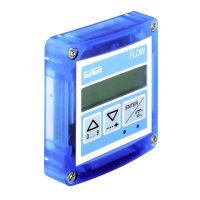
Flow transmitter

Table of Contents

Questions and Answers:

Burkert 8025 Series Specifications

General IconGeneral
TypeFlow Transmitter
CategoryTransmitter
Power Supply12-36 V DC
DisplayLCD
Output4-20 mA, Pulse
Protection ClassIP65
Temperature Range-10 to 60 °C
Pipe DiameterDN06 to DN400
Process ConnectionFlange, Threaded, Clamp
Wetted MaterialsStainless steel
Accuracy±0.5% of measured value
Measuring Range0.3 to 10 m/s
Process PressurePN10/PN16
Housing Materialstainless steel
Electrical ConnectionM12 connector

Summary

1 ABOUT THIS MANUAL

1.1 Symbols used

Explains the symbols used throughout the manual for warnings and notes.

1.2 Definition of the word "device"

Defines the term 'device' as used in the manual for the transmitter type 8025 Universal.

2 INTENDED USE

3 BASIC SAFETY INFORMATION

4 GENERAL INFORMATION

4.1 Manufacturer's address and international contacts

Lists the manufacturer's address and provides information on how to find local sales offices.

4.2 Warranty conditions

Specifies the conditions that govern the legal warranty for the device.

4.3 Information on the Internet

Directs users to the website for manuals and technical data sheets.

5 DESCRIPTION

5.1 Area of application

Explains the functionalities and applications of the flow transmitter.

5.2 General description

Provides an overview of the flow transmitter's design and components.

5.3 Available versions

Lists the different versions of the 8025 Universal transmitter and their specifications.

5.4 Description of the name plate

6 TECHNICAL DATA

6.1 Conditions of use

Specifies environmental and operational conditions for the device.

6.2 Conformity to standards and directives

Lists the standards and directives the device complies with.

6.3.1 Mechanical data

Details the materials used for the device's various components.

6.3.2 Electrical data

Provides detailed electrical specifications for power supply, outputs, and current.

6.3.3 Specifications of the connected flow sensor

Details the signal types, frequency, voltage, and impedance for connected sensors.

6.3.4 Electrical connection

Describes cable specifications, wire cross-sections, and gland diameters.

7 INSTALLATION AND WIRING

7.1 Safety instructions

Provides critical safety warnings for installation and wiring procedures.

7.2 Installation of a panel version

Details the steps for installing the panel version of the transmitter.

7.3 Installation of a wall-mounted version

Provides instructions for mounting and installing the wall-mounted version.

7.4 Wiring

Covers general wiring precautions and specific connection instructions.

7.4.1 Equipotentiality of the installation

Explains how to ensure equipotentiality for safe electrical installation.

7.4.2 Terminal assignment and use of the selectors

Details terminal block assignments and how to use device selectors.

7.4.3 Wiring a panel version

Provides specific wiring instructions for the panel version of the device.

7.4.4 Wiring a wall-mounted version

Provides specific wiring instructions for the wall-mounted version of the device.

7.4.5 Wiring the AO1 current output of a panel version or a wall-mounted version, 12-36 V DC

Details wiring for the 4-20 mA current output in sourcing or sinking mode.

7.4.7 Wiring the AO1 current output of a wall-mounted version, 115/230 V AC

Details wiring for the 4-20 mA output for the 115/230 V AC version.

7.4.8 Wiring the DO1 transistor output of a wall-mounted version, 115/230 V AC

Explains NPN and PNP wiring for the DO1 output on the 115/230 V AC version.

7.4.9 Wiring the relay outputs DO2 and DO3 of the panel or a wall-mounted version

Provides wiring instructions for the DO2 and DO3 relay outputs.

7.4.10 Connecting the flow sensor to the transmitter

Guides on connecting the flow sensor, setting selectors, and terminal assignments.

8 OPERATING AND COMMISSIONING

8.1 Safety instructions

Highlights critical safety warnings for operation and commissioning.

8.2 Operating levels of the device

Explains the two operating levels: Process and Configuration.

8.3 Description of the navigation keys and the status LEDs

Details the function of navigation keys and the meaning of device status LEDs.

8.4 Using the navigation keys

Explains how to use the device's navigation keys for parameter selection and confirmation.

8.5 Details of the Process level

Describes the information displayed and functions available in the Process level.

8.6 Details of the Parameters menu

Introduces the configurable parameters and the structure of the Parameters menu.

8.6.1 Choosing the display language

Guides on how to select and change the device's display language.

8.6.2 Choosing the flow rate units, the number of decimals and the units of the totalizers

Explains how to set flow rate units, decimal places, and totalizer units.

8.6.3 Entering the K factor of the fitting used

Details how to manually enter the K factor for flow rate calculation.

8.6.4 Determining the fitting K factor using a Teach-In procedure

Explains how to automatically determine the K factor using Teach-In methods.

8.6.5 Configuring the outputs (general diagram)

Provides an overview of how to configure the device's outputs (AO1, DO1, DO2, DO3).

8.6.6 Associating a flow rate range to the current output AO1

Details how to map flow rate values to the 4-20 mA current output.

8.6.7 Activating / Deactivating the emission of a 22 mA current on the current output

Explains how to enable or disable the 22 mA fault current emission.

8.6.8 Configuring the transistor output DO1 as a pulse output proportional to a volume

Guides on configuring DO1 for pulse output based on measured volume.

8.6.9 Configuring the transistor output DO1 to transmit the rotational frequency of the paddle wheel

Explains how to configure DO1 to output rotational frequency in Hertz.

8.6.10 Configuring the transistor output DO1 to switch a load depending on two threshold values

Details how to set DO1 to switch a load based on low and high flow rate thresholds.

8.6.12 Configuring the relay outputs DO2 and DO3 to switch a load depending on two thresholds

Details how to set relay outputs based on low and high flow rate thresholds.

8.6.13 Configuring the relay outputs DO2 and DO3 to switch a load when a warning message is generated by the device

Explains how to configure relay outputs to switch load upon a warning message.

8.6.14 Configuring the filter of the measured flow rate

Details how to set filtering parameters to dampen flow rate fluctuations.

8.6.15 Resetting both totalizers

Explains how to reset both the main and daily totalizers.

8.6.16 Parameterizing the cut-off flow rate

Details how to set a cut-off flow rate below which the device reads zero.

8.6.17 Setting the brightness of the display and how long it stays ON, or deactivating the backlight

Covers adjusting display brightness, backlight duration, and deactivation.

8.7 Details of the Test menu

Introduces the Test menu parameters for checking device functions.

8.7.1 Adjusting the current output

Guides on calibrating the 4-20 mA analog output (offset and span).

8.7.2 Reading the rotational frequency of the paddle wheel

Explains how to read the paddle wheel's rotational frequency.

8.7.3 Checking the outputs behaviour

Details how to simulate flow rates to check output functionality.

8.7.4 Monitoring the flow rate in the pipe

Explains how to monitor flow rate and configure warnings for range deviations.

8.7.5 Monitoring the value of the daily totalizer

Details how to monitor the daily totalizer and configure warnings for set value reached.

8.8 Details of the Information menu

Explains how to access and read fault and warning messages from the Information menu.

9 MAINTENANCE AND TROUBLESHOOTING

9.1 Safety instructions

Highlights critical safety warnings for maintenance and troubleshooting.

9.2 Cleaning the device

Provides instructions on how to clean the device safely and effectively.

9.3 If you encounter problems

Offers guidance on diagnosing and resolving common device issues.

9.3.1 Resolution of problems when the device status LED is OFF

Troubleshooting steps for when the device status LED is off.

9.3.2 Resolution of problems without message generation and device status LED red

Troubleshooting steps for red LED status without specific message generation.

9.3.3 Resolution of problems without message generation and with device status LED orange

Troubleshooting steps for orange LED status without specific message generation.

9.3.4 Resolution of problems without message generation but device status LED ON

Troubleshooting steps for when the device status LED is ON but no message is shown.

9.3.5 Resolution of problems without message generation and with device status LED green

Troubleshooting steps for green LED status without specific message generation.

9.3.6 Resolution of problems linked to warning messages not registered in the Information menu

Troubleshooting for issues related to warning messages not in the Information menu.

10 SPARE PARTS AND ACCESSORIES

11 PACKAGING, TRANSPORT

12 STORAGE

13 DISPOSAL OF THE PRODUCT

Related product manuals