Installation | 4
0870524638_RA_Aqua_A0003_IMS_en 7 / 12
4 Installation
4.1 Connecting Lines / Pipes
• Remove all protective covers before installation.
• Make sure that the connection lines cause no stress on the machine‘s connection; if
necessary use flexible joints.
• Make sure that the line size of the connection lines over the entire length is at least as
large as the connections of the machine.
In case of very long connection lines it is advisable to use larger line sizes in order to
avoid a loss of efficiency. Seek advice from your Busch representative.
4.1.1 Suction Connection
Connection size(s):
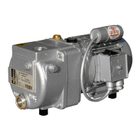
– Ø60 mm hose for RA 0165-0305 D
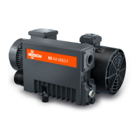
– Ø90 mm hose for RA 0400-0630 C
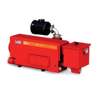
– DN150 PN16, EN 1092-1 for RA 1000-1600 B
The inlet connection may be equipped with a ball valve.
Depending on the specific order, other connection dimensions may apply.
4.1.2 Discharge Connection
Connection size(s):
– G2 for RA 0165-0305 D
– G3 for RA 0400-0630 C
– 2x DN125 PN16, EN 1092-1 for RA 1000-1600 B
Depending on the specific order, other connection dimensions may apply.
4.2 Electrical Connection of the Monitoring Devices
4.2.1 Wiring Diagram Temperature Switch "Oil"
Part no.: 0651563747
Connector: M12x1, 4-pin
Electrical data:
U = ≤ 250 V AC/DC (50/60 Hz) ; I = ≤ 1 A
Switch point:
T
1
pin 1 + 2 = 110 °C*
T
2
pin 3 + 4 = 130 °C*
1 = Brown ; 2 = White ;
3 = Blue ; 4 = Black
* The switch point value depends on the oil type, see Oil [►8].
 Loading...
