BW Broadcast technical manual
Page 23
Installation and setup
ADVANCED SETUP PROCEDURE
The front panel LCD metering is accurate enough to set up the transmitter in the absence of external test equip-
ment. If you have access to a modulation meter and RF power meter then substitute those for references to the
relevant LCD display menu.
You will most likely need the following pieces of test equipment:
Audio signal generator capable of -10dbu to +10dbu
Voltmeter
2.52 Multiplex input only.
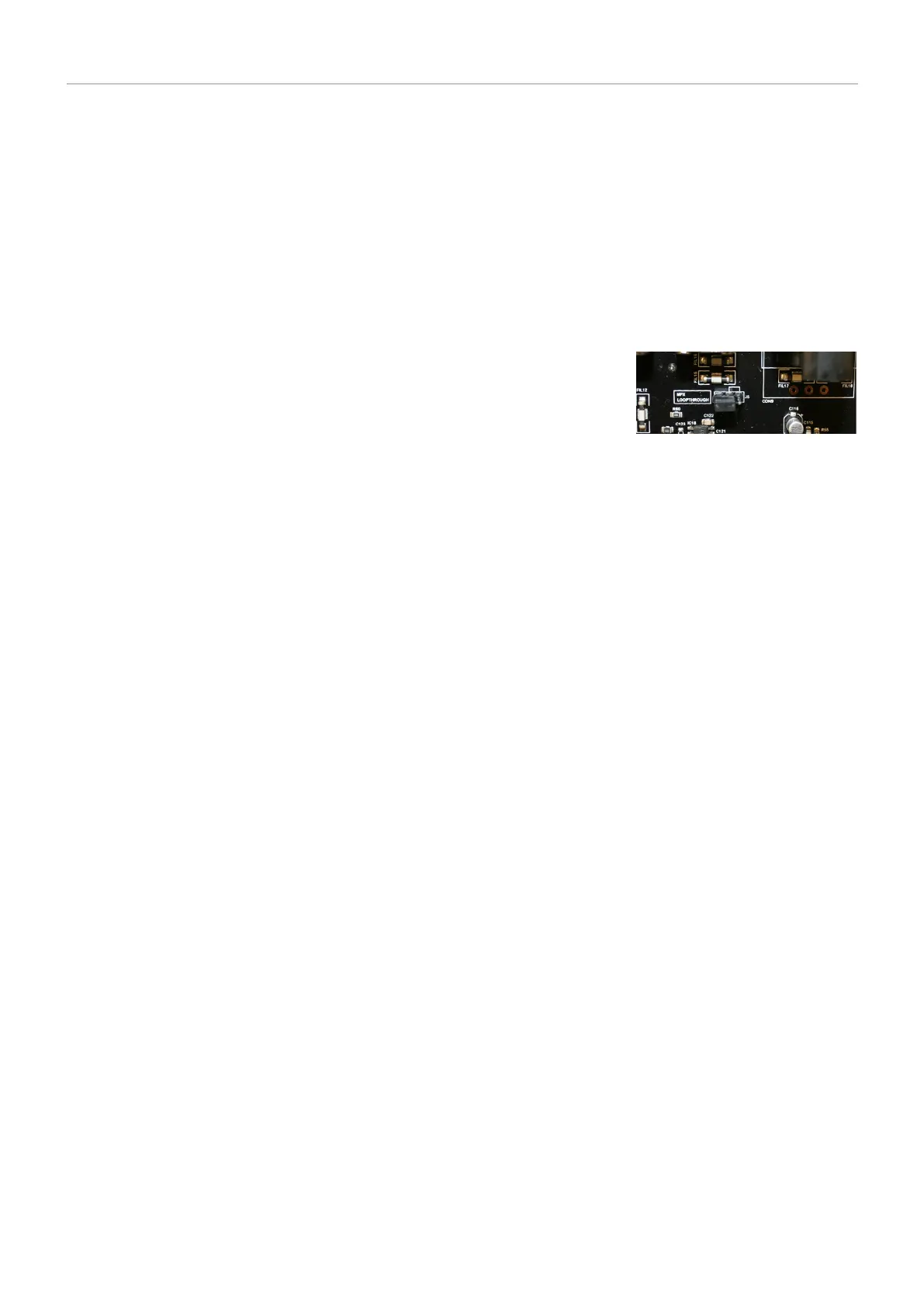
Open the lid of the transmitter and make sure that jumper J5 on the main board
is configured so that MPX Loopthrough is OFF. This makes sure that the internal
stereo encoder is not connected through to the modulator. Connect your wide-
band audio source (processor, coder or rebroadcast receiver) to the multiplex
input on the back panel. Setup your external equipment for its correct output
level making sure that it falls into the range of -6 to +10 dbu. Adjust the multi-
plex input level control on the back panel for a peak deviation of +/- 75kHz. The
peak deviation can be shown on the LCD system.
The factory setting for the multiplex input level is +6dBu. This corresponds to the
output level of our internal stereo encoder module. We recommend feeding this level input to the multiplex input
socket if it is available from the external equipment.
2.53 Stereo.
The limiter can be disabled internally if you do not require it. This effectively allows any audio input signals
straight through to the stereo encoder unaltered. You may wish to disable the limiter when you have an external
processor or limiter that may be of a higher performance than the internal limiter in this transmitter. You can still
have the limiter active even with external limiters in operation. We leave that up to you. For safety purposes you
may wish to leave the clippers on the limiter and the 15 kHz filters in to provide extra protection when you are
unsure of the peak output characteristics of the external piece of equipment. When you know that the piece of
audio processing equipment is band-limited to 15 kHz and peak limited you can leave out the clippers safe in the
assumption that the external processor will be able to handle the level control completely.
Advanced setup procedure.
1. Firstly make sure that the exciter is set to your chosen operating frequency. If you have not already done so
then remove the top cover from the transmitter.
2. Connect the transmitter to a dummy load.
3. Turn on the transmitter and within 10 seconds it should lock to frequency.
4. If your audio feed has gone through an external processor prior to this transmitter then check to see if that unit
has pre-emphasis capability and if it is switched on. If it has pre-emphasis and it is enabled then you should set
the transmittor pre-emphasis DIP switch, set to off to ensure that only one set of pre-emphasis has been applied
throughout the broadcast chain. Otherwise, switch it to on and set DIP switch 2 to the correct setting for your
region, 75µs for the Americas and Japan and 50µs for the rest of the world. Turn the pre-emphasis off for now by
setting DIP switch 1 to the right. Make sure the loopthrough jumper J5 is switched to loopthrough and DIP switch
3 is set to stereo. Disable the stereo pilot by setting jumper J6 to mono.
These settings will allow any audio straight through the limiter and into the stereo encoder without any form of
level control apart from the peak level clippers, so we can set the system internal levels correctly.
5. Connect an audio source to both channels and apply a 400Hz tone with a level of +6dBu.
MPX Loopthrough Jumper
in off position
 Loading...