Do you have a question about the BW Broadcast TX1000 and is the answer not in the manual?
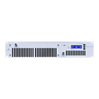
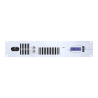
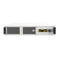
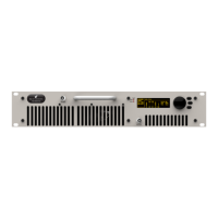
Overview of the BW Broadcast TX1000+/1500+ FM transmitter's features and capabilities.
Details the manufacturer's warranty terms, conditions, and claim procedures for the transmitter.
Critical safety precautions for operating the FM broadcast transmitter, including electrical and RF hazards.
Step-by-step guide for quickly setting up the transmitter for basic operation.
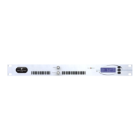
Identification and description of all connectors, controls, and indicators on the front and rear panels.
Description of the front panel LCD graphics display screens for monitoring and control.
Instructions on how to set the transmitter's operating frequency using internal switches or the front panel.
Guidance on adjusting and controlling the RF output power of the transmitter.
Explanation of the transmitter's alarm system, including RF Power, PLL Lock, and Modulation Failure.
Procedures for controlling and monitoring the transmitter remotely via RS232 interface.
Using the Windows Remote Control application for transmitter monitoring and control.
Connecting and operating the transmitter using a standard serial terminal program.
Overview of different operational modes and how to configure them using jumpers and switches.
Explanation of internal jumpers and DIP switches for configuring hardware settings and modes.
Detailed steps for advanced transmitter setup and calibration without external test equipment.
Additional setup considerations, including loopthrough connections and frequency fine-tuning.
Comprehensive technical specifications for the TX1000/TX1500 FM Broadcast Transmitter.
Detailed explanation of the transmitter's internal circuitry and electronic components.
Details the Combo board's circuitry, including audio limiter and stereo encoder functions.
Explains the exciter section, covering frequency determination and amplification stages.
Focuses on the LCD control board, its microcontroller, display, and interface functions.
Describes the Power Amplifier board, including PSU interface, bus bar, and fan connections.
Details the PA 15W driver board, including RF signal path and impedance matching.
Explains the double pallet amplifier stages, bias control, and output distribution.
Visual block diagram illustrating the transmitter's internal signal flow and component connections.
Overview of the transmitter's internal wiring layout and component placement.
Detailed schematic diagrams of the transmitter's electronic sections.
Schematic for the DSP Limiter section of the combo board.
Schematic diagram for the stereo encoder section of the combo board.
Schematic detailing the PLL exciter section, including frequency control and loop filter.
Schematic for the digital audio input section, covering AES/EBU interface.
Comprehensive list of all parts used in the transmitter's various boards and assemblies.
List of components for the Combo board.
Component list for the LCD control board.
Parts list for the PSU Interface board.
Component list for the Bus Bar board.
Parts list for the Fan connector board.
Component list for the D to IDC board.
List of components for the Controller board.
Parts list for the 15W Driver board.
Component list for the Double Pallet amplifier.
Parts list for the Output Combiner section.
| Power Output | 1000 W |
|---|---|
| Frequency Range | 87.5 - 108 MHz |
| Modulation | FM |
| Cooling | Forced Air |
| Dimensions | 19" x 3.5" x 16" |
| RF Output Power | 1000 W |
| RF Output Connector | N-type |
| MPX Input | BNC |
| Output Power | 1000 W |
| Input Connector | XLR, RCA |
| Output Connector | N-type |
| Power Supply | Internal |
| Audio Inputs | XLR, RCA |
| Audio Input | XLR, RCA |
| Power Requirements | 220-240 V AC |