GB
1313
1313
13
Installation conditionsInstallation conditions
Installation conditionsInstallation conditions
Installation conditions
Observe all applicable installation regulations and technical specifica-
tions. In some countries a system separation is necessary when install-
ing this filter.
The filter is not suitable for producing drinking water from water of
unknown origin.
A strainer of 200 μm must be installed upstream of the filter.A strainer of 200 μm must be installed upstream of the filter.
A strainer of 200 μm must be installed upstream of the filter.A strainer of 200 μm must be installed upstream of the filter.
A strainer of 200 μm must be installed upstream of the filter.
The water to be filtered must be drinking water that fulfils the following
quality criteria:
Free chlorine < 2 ppm
Temperature 4°C – 30°C
Maximum static pressure: 8 bar
Minimum flow pressure: 2.5 bar
The unit’The unit’
The unit’The unit’
The unit’
s maxims maxim
s maxims maxim
s maxim
um operum oper
um operum oper
um oper
ational pressure mational pressure m
ational pressure mational pressure m
ational pressure m
ust neust ne
ust neust ne
ust ne
vv
vv
v
er be eer be e
er be eer be e
er be e
xceededxceeded
xceededxceeded
xceeded
(see above).
If the network pressure is higher, a pressure reducer must
be installed upstream of the unit.
The unit requires a minimum operational pressure in order to function.The unit requires a minimum operational pressure in order to function.
The unit requires a minimum operational pressure in order to function.The unit requires a minimum operational pressure in order to function.
The unit requires a minimum operational pressure in order to function.
During pressure fluctuations or surges, the sum of the pressure surgeDuring pressure fluctuations or surges, the sum of the pressure surge
During pressure fluctuations or surges, the sum of the pressure surgeDuring pressure fluctuations or surges, the sum of the pressure surge
During pressure fluctuations or surges, the sum of the pressure surge
and the standing pressure mand the standing pressure m
and the standing pressure mand the standing pressure m
and the standing pressure m
ust not eust not e
ust not eust not e
ust not e
xceed the nominal pressurexceed the nominal pressure
xceed the nominal pressurexceed the nominal pressure
xceed the nominal pressure
..
..
. The
positive pressure surge must not be greater than 2 bar, and the negative
pressure surge must not be less than 50% of the self-adjusting flow
pressure.
When installing the unit, select a location where the unit can easily be
connected to the water supply network. A connection to the sewage system
(at least DN 50), a floor drain and a separate power supply (230 V/50 Hz)
must be located in the immediate vicinity.
The flushing water hose must be routed at an incline to the sewage system
or connected to a pump.
Note:Note:
Note:Note:
Note:
The flushing water hose must be connected
at least 20 mm above the highest possible waste water level (unimpeded
drainage).
The installation site must be protected against frost and mustThe installation site must be protected against frost and must
The installation site must be protected against frost and mustThe installation site must be protected against frost and must
The installation site must be protected against frost and must
guarantee the protection of the filter from water splashes, solventguarantee the protection of the filter from water splashes, solvent
guarantee the protection of the filter from water splashes, solventguarantee the protection of the filter from water splashes, solvent
guarantee the protection of the filter from water splashes, solvent
vapours, fuel oil, soap sud, chemicals of all types, UV irradiationvapours, fuel oil, soap sud, chemicals of all types, UV irradiation
vapours, fuel oil, soap sud, chemicals of all types, UV irradiationvapours, fuel oil, soap sud, chemicals of all types, UV irradiation
vapours, fuel oil, soap sud, chemicals of all types, UV irradiation
(sunlight), and heat sources over 40°C.(sunlight), and heat sources over 40°C.
(sunlight), and heat sources over 40°C.(sunlight), and heat sources over 40°C.
(sunlight), and heat sources over 40°C.
InstallationInstallation
InstallationInstallation
Installation
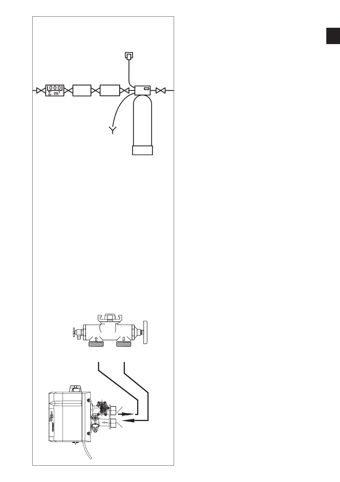
Connect the unit as shown in the adjacent diagram.
A bypass is integrated into multiblock module.
Installation is possible in horizontal or vertical pipelines.
Follow the separate installation instructions; otherwise the warranty is
void if the unit becomes damaged.
Flush out any dirt particles by opening the handwheel on the multiblock
module.
Connect a corrugated hose to the multiblock module
outletoutlet
outletoutlet
outlet and the
hardhard
hardhard
hard
water inletwater inlet
water inletwater inlet
water inlet (
77
77
7).
Be sure to observe the arrows indicating the direction ofBe sure to observe the arrows indicating the direction of
Be sure to observe the arrows indicating the direction ofBe sure to observe the arrows indicating the direction of
Be sure to observe the arrows indicating the direction of
floflo
floflo
flo
ww
ww
w.
Connect a corrugated hose to the multiblock module
inletinlet
inletinlet
inlet and form a
watertight seal with the
softened water outletsoftened water outlet
softened water outletsoftened water outlet
softened water outlet (
66
66
6).
Route the flushing water hose (
1111
1111
11) at an incline to the sewage system
connection (drain) and secure the end with the supplied fixing material to
prevent it flapping about when under pressure.
The flushing water hose must be connected to the channel with aThe flushing water hose must be connected to the channel with a
The flushing water hose must be connected to the channel with aThe flushing water hose must be connected to the channel with a
The flushing water hose must be connected to the channel with a
distance of at least 20 mm from the highest waste water leveldistance of at least 20 mm from the highest waste water level
distance of at least 20 mm from the highest waste water leveldistance of at least 20 mm from the highest waste water level
distance of at least 20 mm from the highest waste water level
(unimpeded drainage).(unimpeded drainage).
(unimpeded drainage).(unimpeded drainage).
(unimpeded drainage).
StrainerStrainer
StrainerStrainer
Strainer
66
66
6
77
77
7
MultiblockMultiblock
MultiblockMultiblock
Multiblock
EingangEingang
EingangEingang
Eingang
zu 6zu 6
zu 6zu 6
zu 6
AusgangAusgang
AusgangAusgang
Ausgang
zu 7zu 7
zu 7zu 7
zu 7
System-System-
System-System-
System-
trennertrenner
trennertrenner
trenner
 Loading...