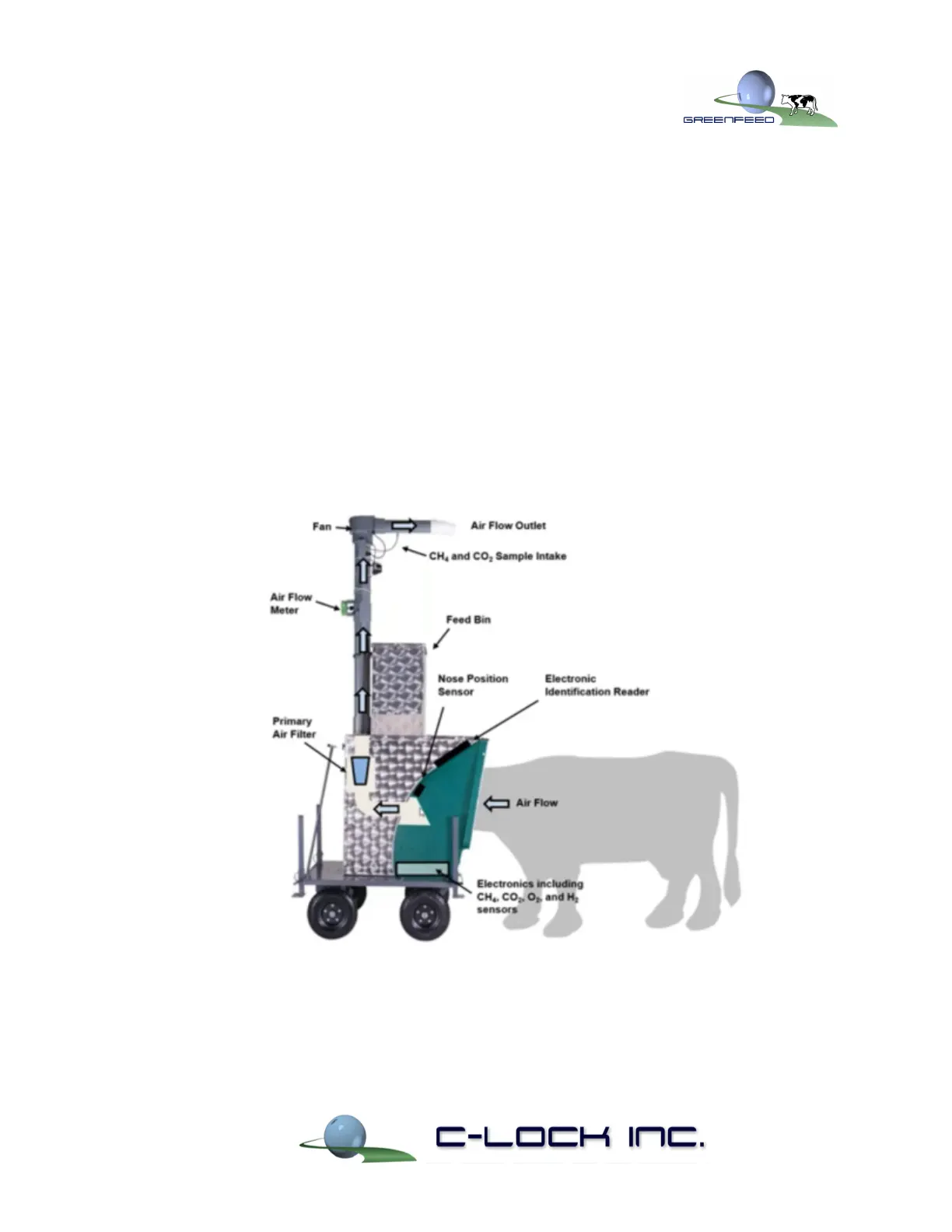
1.2. GreenFeed Component Layout
Figure 3 shows the layout of GreenFeed, including the essential components. Note the path
of the animal’s emissions:
1) From the animal muzzle, the air is collected through the feeding dish up through the
primary air filter - where debris and large particles are removed
2) Next it is directed through the pipe past the air flow meter - this sensor is used to
measure the air velocity, represented as Q
air
in the equation from section 1.1
3) The air continues flowing upward through the fan, which introduces more eddie
currents to ensure a homogenous mixture of the gas.
4) The fan exhausts the air out the outlet, but before exiting, a subsample of the gas is
collected just before the air flow outlet.
5) The subsample is pumped from the fan exhaust down to the bottom of the system,
passing through a secondary filter to remove finer debris, then into the electronics
box, where the sample is processed for gas concentrations.
Figure 3) Sensors and Layout of Included Components in the Stand-Alone GreenFeed