Do you have a question about the C-TEC AlarmSense CFP702-2 and is the answer not in the manual?
Details AlarmSense™ zone circuits, wiring, and device compatibility.
Describes the four conventional sounder circuits for external sounders.
Covers user access levels and available engineering functions.
Crucial instructions for skilled personnel, handling of manual.
Recommends consulting qualified persons for system design and standards.
Outlines conditions for equipment guarantee based on installation.
Specifies indoor installation, height, and positioning for visibility.
Step-by-step guide to remove Main Control and Power Supply PCBs.
Essential precautions for handling static-sensitive electronic components.
Details cable requirements, screening, and glanding for EMC compliance.
Specifies mains supply wiring, cable size, and earthing.
Guidance on planning cable entry points and segregation from mains voltage.
Details number of circuits and maximum devices per circuit.
States AlarmSense™ device compatibility and sounder status programming.
Details the connection of EOL capacitors for circuit monitoring.
Explains wiring for conventional sounders, EOL resistors, and polarity.
Specifies maximum total sounder current and per-zone limits.
Advises distributing sounder load equally across circuits.
Describes ALERT input (intermittent) and CLASS CHANGE input (continuous).
Details RESET, REMOTE, AUX 24V, AUX, and FAULT outputs and their functions.
Advises on using suitable relays and avoiding door holder circuits.
Guides on checking circuits and installing Power Supply PCB safely.
Instructions for mains connection and safe installation of standby batteries.
Routing mains cable, segregating, and connecting PSU earth strap.
Warning about live voltages present under covers.
Shows how to arrange and secure batteries of different sizes.
Details connecting battery leads to the Power Supply PCB.
Guides on PCB placement, connecting cables, and optional expansion devices.
Advises careful reconnection of 5mm connector blocks and labelling for clarity.
Directs to relevant pages for typical zone and sounder circuit diagrams.
Instructions for connecting auxiliary cables to the Main Control PCB.
Explains proper earthing of screens using the base distribution post.
Describes General User (Lvl 1), Authorised User (Lvl 2), and Engineer (Lvl 3) controls.
Lists functions like coincidence, delays, and fault diagnosis available to engineers.
Explains the non-EN54-2 compliant coincidence feature for zone pairs.
Details the non-EN54-2 compliant feature for zones that don't retain alarm state.
How to set delays (1-10 mins) for sounders and outputs, and override conditions.
Describes the 'one man walk test' facility for commissioning and maintenance.
How to configure sounders to resound or not resound on new alarms, and fit status.
How to use buttons like ACCESS LEVEL THREE FUNCTIONS and NEXT OPTION.
How to access level 2 controls even with the lid removed.
Step-by-step guide to setting up zone pairs for coincidence mode.
Steps to configure zones for non-latching operation, noting non-compliance with EN54-2.
Detailed steps for setting delay periods for zones, remote, and auxiliary outputs.
Guide to setting zones for testing and the required pre-test action.
How to configure sounder resound behavior and sounder fitting status per zone.
Explains General Fault, Supply Present lights and their basic meanings.
Lists potential causes for a Power Supply Fault indication.
Describes indications for system issues and repeater communication faults.
Details fault indications for sounder circuits and remote output.
Steps to diagnose detector head removal, open, and short circuit faults.
Recommended actions for correcting zone wiring faults.
Symptoms and actions for low mains voltage, fuse rupture, or PSU failure.
Symptoms and suggested actions for a ruptured battery fuse.
Explains faults due to low voltage, deep discharge, or battery condition.
Addresses scenarios where the Supply Present light is not lit.
How to identify Watchdog, Site Memory, or PLL faults and their resolution.
Provides the formula to calculate required battery capacity for standby time.
Defines quiescent current (P), zone device current (Z), and alarm current (A).
Illustrates battery capacity calculations with practical examples.
Details voltage, current, fuses, and battery requirements for the power supply.
Covers circuit numbers, cable length, monitoring, impedance, and device limits.
Lists specs for conventional sounder circuits, EOL resistors, and fuses.
Details specifications for auxiliary outputs and inputs.
Covers product dimensions, construction, IP rating, and operating environment.
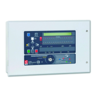
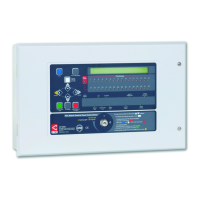
The LPCB Approved CFP 2/4/8 Zone Fire Alarm Control Panel is a sophisticated fire detection and alarm system designed for use in various building types. It offers a comprehensive set of features for both fire and security applications, with models available for two, four, or eight AlarmSense™ zone circuits.
The primary function of the panel is to detect fire conditions and activate alarms. Its AlarmSense™ zone circuits are a key feature, allowing detectors, manual call points, and sounders to be connected on the same two wires, which can lead to significant savings in cabling and installation labor compared to conventional four-wire systems. It's crucial to note that only AlarmSense™ devices are compatible with these zone circuits.
In addition to the AlarmSense™ zone circuits, the panel includes four conventional sounder circuits designed for use with non-AlarmSense™ sounders. These circuits provide the flexibility to integrate a wider range of alarm devices into the system.
The panel also incorporates two non-latching auxiliary input connections: "Alert" and "Class Change." The "Alert" input operates sounders intermittently when connected to 0V, while the "Class Change" input operates sounders continuously when connected to 0V. Neither of these inputs will trigger the panel's remote or auxiliary fire outputs.
For external control and integration, the panel offers several auxiliary outputs. These include a Reset output (RESET), a Remote output (REM), an Auxiliary 24V output (AUX 24V), an Auxiliary Fire Output (AUX), and a Fault Output (FAULT). The Reset output activates during the panel's reset cycle, useful for resetting other fire alarm system devices. The Remote output activates during any new fire alarm condition or when the Silence/Resound Sounders button is pressed for manual evacuation, but not from Class Change or Alert inputs unless other fire alarm conditions are present. The Auxiliary 24V output provides a positive voltage supply for peripheral loads, protected by a current-limiting fuse. The Auxiliary Fire Output activates during any fire alarm condition and deactivates upon reset, but not from Class Change or Alert inputs or manual evacuation unless other fire conditions exist. The Fault Output is normally energized and turns off when a fault occurs, ensuring fail-safe operation even during total power loss.
The panel offers three control levels: general user (access level 1), authorized user (access level 2), and engineer (access level 3).
General user controls (access level 1) provide a clear overview of the system's status, displaying fire and fault conditions and output statuses. Users at this level can mute the internal sounder, override programmed delays, and access authorized user controls.
Authorized user controls (access level 2) are accessible via a keypad code or keyswitch and allow for silencing sounders, resetting alarms, manually activating sounders for evacuation, testing indicator lights, and enabling/disabling zones, sounders, fault output, remote output, auxiliary fire output, and delays.
Engineer controls (access level 3) provide access to site-specific data and advanced programming functions. These include programming coincidence (double-knock) for specific zone pairs, setting up non-latching zones, programming delays for sounders and outputs, invoking test procedures, configuring sounder resound behavior for new alarms, and programming whether sounders are fitted on zone circuits.
A "coincidence" or "double-knock" feature can be programmed for zone pairs, requiring alarms on both zones before sounders and outputs activate. If only one zone alarms, the panel indicates the condition and sounds its internal sounder for investigation. This feature is non-compliant with EN54-2.
Non-latching zones can be configured to automatically clear alarm conditions once the stimulus is removed, without requiring a manual panel reset. Alarms from non-latching zones will not trigger auxiliary fire and remote outputs. This function is also non-compliant with EN54-2.
A delay of 1 to 10 minutes can be set between an alarm condition and the activation of sounders and outputs. This delay is adjustable via a VR1 control on the Main Control PCB. During the delay, the "Output Delays" light pulses, and pressing the Silence/Resound Sounders button will override the delay.
A "one man walk test" facility is available for commissioning and maintenance. When zones are in test mode, alarm sounders operate intermittently for approximately one second on and eight seconds off, continuing until the alarm cause is removed. This allows for checking multiple devices efficiently.
The panel can be programmed to either resound or not resound sounders when a new alarm is raised from a different zone after sounders have been silenced. Additionally, zone circuits can be programmed to indicate whether AlarmSense™ sounders are fitted or not.
The panel includes comprehensive fault diagnostic facilities accessible at access level 3. When a fault occurs, the internal sounder activates, the "General Fault" light illuminates, and specific fault lights provide detailed information. Faults typically indicated include zone faults (open/short circuit, detector head removal), power supply faults (Mains supply issues, fuse ruptures, low battery voltage, faulty PSU), system faults (microprocessor watchdog fault, site memory corruption, PLL fault), repeater faults, conventional sounder faults, and remote output faults.
The panel's power supply PCB monitors the supply and battery charging. The standby batteries are protected against deep discharge by a cut-off circuit. If batteries are not fitted, discharged, or in poor condition, a PSU fault will be indicated.
Periodic system maintenance, as prescribed by local regulations, is essential. This includes checking standby batteries for connection integrity, signs of venting, and performing a load test with the Mains supply disabled to ensure adequate capacity. Batteries should be renewed if their integrity is in doubt.
The manual provides detailed instructions for diagnosing and rectifying various fault conditions, including steps for checking wiring, fuses, and PCB components. It also outlines procedures for programming and configuring the panel's advanced features, emphasizing the importance of updating the System Set-Up Data chart in the User Manual/Log Book after any changes.
| Type | Conventional Fire Alarm Control Panel |
|---|---|
| Number of Zones | 2 |
| Input Voltage | 230V AC |
| Frequency | 50 Hz |
| Battery Size | Up to 7Ah |
| Operating Temperature | -5°C to +40°C |
| Approval | EN54-2 & EN54-4 |
| Weight | 3.5kg |
| Standards | EN54-2/4 |