Do you have a question about the C-TEC CAST XFP and is the answer not in the manual?
Lists the components included in the panel package, including manuals and accessory packs.
Guidance on fire alarm system design, consultation with professionals, and relevant standards.
Specifies recommended cable types and limitations for installation, including fire resistance and screening.
Confirms panel compliance with EN54 Parts 2 and 4 standards, certified by LPCB.
Outlines conditions for equipment guarantee, requiring installation by competent persons.
Provides essential precautions for handling static-sensitive components to prevent damage.
Details the panel's optional network capabilities for connecting multiple panels or repeaters.
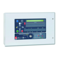
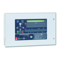
Describes the panel's enclosure, mounting considerations, and internal space for components.
Step-by-step instructions for safely removing internal PCBs for installation.
Guidance on physically mounting the panel enclosure onto a wall surface or flush.
Advice on organizing and routing cables within the panel for clarity and safety.
Instructions for connecting the panel's mains power supply, including wiring regulations.
Detailed guide on connecting mains supply to the PSU PCB, including safety precautions.
Explains how to wire the analogue addressable loop devices to the panel.
Specific instructions for connecting the loop wiring to the Main Control PCB terminals.
Details on wiring the panel's conventional sounder circuits for alarm notification.
Guide on connecting external auxiliary inputs to the panel for monitoring.
Instructions for wiring the panel's programmable relay outputs for external signalling.
How to connect a PC for programming the panel's functions and configuration.
Information on the auxiliary 24V DC output for powering ancillary equipment.
Instructions for installing and connecting the required standby batteries for power backup.
Overview of the control buttons and display elements on the panel's front interface.
Explains the status indicated by various LEDs on the panel, including Fire, Fault, and Supply status.
Describes the function of each control button on the panel for navigation and operation.
Details the function and operation of the panel's keyswitch for access level control.
A step-by-step guide for the initial setup, testing, and configuration of the panel.
Overview of the panel's menu hierarchy and different access levels for users and engineers.
Detailed steps to access the engineer-level functions using codes or keyswitch.
Instructions on installing the NVM 'memory unlock' link for site-specific configuration.
Procedure to disable the panel's internal sounder, noting non-compliance with EN54-2.
Location and function of the reset button for panel recovery and rebooting.
Function to view active fire conditions and event details on the panel display.
Function to view active fault conditions and details on the panel display.
Function to view currently disabled zones, sounders, or devices on the system.
Function to view which zones are currently in a test mode or state.
Procedure for changing access level codes for enhanced system security.
Activates the panel's PC connection for programming and configuration via software.
Configuration options for networking the panel with other CAST XFP panels or repeaters.
Process to interrogate and identify pre-addressed devices on an analogue loop.
Menu for managing device addresses, including auto-addressing and fixing duplicates.
Automatically assigns addresses to devices on the loop in sequential order.
Function to replace a faulty loop device or add a new device to the system.
Allows changing the address of a specific loop device directly from the panel.
Helps locate devices with duplicate addresses by activating their LEDs.
Procedure to resolve duplicate device addresses found on the loop.
Detects swapped loop devices, new devices, or loop configuration changes.
Lists addressable devices stored in the panel's memory, showing device type and address.
Assigns loop devices to specific zones or sounder groups for system logic.
Configures the times for the panel to switch between occupied and unoccupied modes.
Allows programming the panel for automatic Daylight Saving Time adjustments.
Sets sounder groups to be globally or individually disabled or enabled.
Enables a mode to detect if loop devices have been physically swapped.
Controls the global status of device polling LEDs, allowing them to be turned on or off.
Resets the panel's memory to factory default settings with a confirmation code.
Re-initializes the loop to resolve issues with missing or unresponsive devices.
Allows disabling specific zones from reporting faults or fires, e.g., for nuisance tripping.
Disables specific sounder groups from activating during a fire condition.
Disables specific output sets from activating, e.g., for maintenance of ancillary systems.
Disables auxiliary relays from activating as programmed, for specific control needs.
Disables individual loop devices from reporting faults or fires, e.g., for nuisance tripping.
Suppresses the panel's fault relay output from activating during a fault condition.
Globally enables or disables programmed delays for system outputs.
Views the current analogue status and details of any addressable device on the system.
Asserts device outputs (like LEDs) to verify their correct functioning.
Tests system output sets by changing their state from Normal to Triggered.
Tests sounder groups by altering their state between Silenced, Intermittent, and Continuous.
Tests Visual Alarm Device (VAD) groups by altering their state from Normal to Triggered.
Tests the panel's three volt-free relays to ensure they are functioning correctly.
Puts detection zones into walk test mode to verify detector and sounder operation.
Helps pinpoint the location of loop wiring breaks or short circuits by indicating device LEDs.
Identifies loop wiring faults by continually polling devices and reporting poll status.
Views the panel's database of loop devices, including type, address, and description.
Displays panel firmware version, bootloader, and site data last changed date.
Displays information on the Power Supply Unit (PSU) status and standby battery.
Temporarily disables the panel's earth fault monitoring circuitry.
Interrogates and views information held by CAST devices, such as parameters and flags.
Assists with fault-finding by turning device polling LEDs on or off.
Provides a guide or tool reference for calculating required battery capacity for standby time.
| Enclosure Rating | IP30 |
|---|---|
| Type | Addressable Fire Alarm Panel |
| Programming | Via PC Software |
| Compliance | EN54-2, EN54-4 |
| Input Voltage | 230V |
| Compatibility | C-TEC |