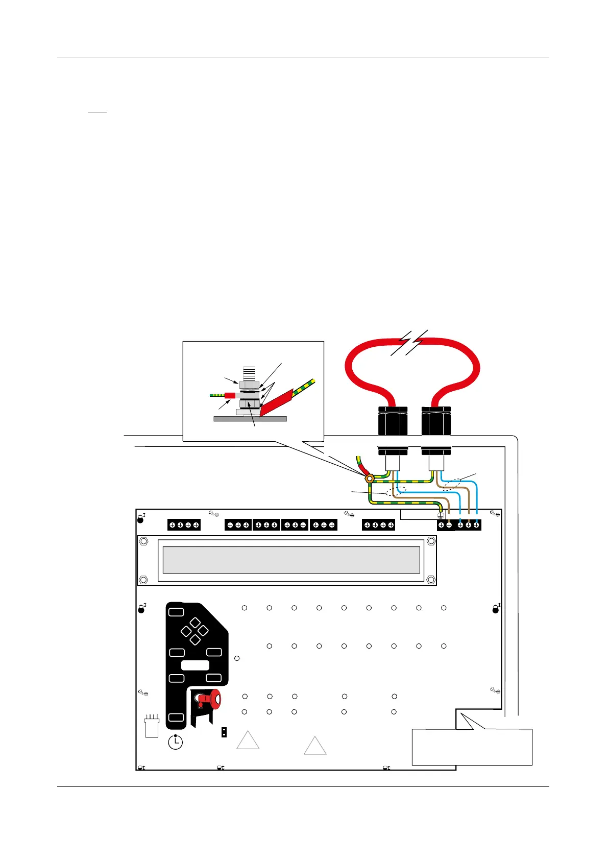
Connecting the analogue loop to the Main Control PCB
One analogue loop is provided which is capable of supporting up to 255 addressable devices.
The analogue loop should be connected to the Main Control PCB terminals marked: A+, A- (LOOP
1A OUT) and B+, B- (LOOP 1B RETURN), as shown in Fig.5 below. The loop’s earth screens should be
connected to the base earth distribution post.
Note that the Main Control PCB connects to the Power Supply PCB via an 8-way telecoms-style connector
cable, the socket for which is located on the PCB’s rear. This cable MUST be connected before the Main
Control PCB is secured in the panel.
Note about earthing of screens
All screens should be adequately insulated and connected between the nut and washers on the
base earth distribution post using crimp connectors. The base earth distribution post is provided for
terminating earth screens or drains and is NOT the main earthing point. The installer must review the
external earth bonding (if required) with respect to the national wiring rules. If the installation requires
protective earth bonding, then this must be applied externally and in conjunction with the type of
earthing system employed on site.
Fig.5 : Typical analogue addressable loop connection
GENERAL
FIRE
ZONE 1
ZONE 2
ZONE 3
ZONE 4
ZONE 5
ZONE 6
ZONE 7
ZONE 8
ZONE 9
ZONE 10
ZONE 11
ZONE12
ZONE 13
ZONE 14
ZONE 15
ZONE 16
SUPPLY
PRESENT
TEST
ACCESSED
GENERAL
DISABLEMENT
PHASED
EVACUATION
GENERAL
FAULT
PSU
FAULT
SYSTEM
FAULT
SOUNDER
STAT US
DELAYS
RUNNING
Auxilliary
+24V I/P1 I/P2 0v
Relay 1
NC C NO
Relay 2
NC C NO
Relay 3
NC C NO
Fault
NC C NO
Sounder Circuits
+ 1 -
+ 2 -
Earth Fault Detect
REMOVING THIS CIRCUIT
BOARD EXPOSES HAZARDOUS
VOLTAGES - PLEASE REFER TO
INSTALLATION INSTRUCTIONS
WARNING
SENSITIVE TO STATIC
ELECTRICITY - OBSERVE
PRECAUTIONS BEFORE
HANDLING
CAUTION - RISK OF EXPLOSION IF
INCORRECT TYPE OF BATTERIES FITTED.
DISPOSE OF USED BATTERIES ACCORDING
TO THE MANUFACTURERS INSTRUCTIONS.
FOR OPERATIONAL DETAILS PLEASE
CONSULT THE MAINTENANCE MANUAL
Mute
Beeper
A
B
+
-
+
-
nut
3 x plain
washer
crimped
connection
Do not untighten lower nut
spring
washer
screens
Base Distribution Earth Post
PSU Earth
Distribution
Strap
Analogue Loop
LOOP 1A (OUT)
LOOP 1B (RETURN)
END A+
END A-
END B-
END B+
Earth
CONN1
Program
PLK3
Memory
Unlock
Connector cable (connects
from rear of Main Control PCB
to PL1 on Power Supply PCB)
ENGINEERING MANUAL • Approved Document No. DFU5010000 Rev 4 • Page 9 of 48
CAST XFP 16 ZONE ANALOGUE ADDRESSABLE FIRE ALARM PANEL
PSU Earth
Distribution Strap