POLARISED
SOUNDER
+ + +
-
+
+
✗
POLARISED
SOUNDER
POLARISED
SOUNDER
EOL
Resistor
(6k8 ohm)
DO NOT SPUR
(Wiring not monitored)
SOUNDER
CCT 1
GENERAL
FIRE
ZONE 1
ZONE 2
ZONE 3
ZONE 4
ZONE 5
ZONE 6
ZONE 7
ZONE 8
ZONE 9
ZONE 10
ZONE 11
ZONE12
ZONE 13
ZONE 14
ZONE 15
ZONE 16
D45
SUPPLY
PRESENT
TEST
ACCESSED
GENERAL
DISABLEMENT
PHASED
EVACUATION
GENERAL
FAULT
PSU
FAULT
SYSTEM
FAULT
SOUNDER
STATUS
DELAYS
RUNNING
Auxilliary
+24V I/P1 I/P2 0v
Relay 1
NC C NO
Relay 2
NC C NO
Relay 3
NC C NO
Fault
NC C NO
Earth Fault Detect
Addressable Loop
+ A -
+ B -
REMOVING THIS CIRCUIT
BOARD EXPOSES HAZARDOUS
VOLTA GES - PLEASE REFER TO
INSTALLATION INSTRUCTIONS
WARNING
SENSITIVE TO STATIC
ELECTRICITY - OBSERVE
PRECAUTIONS BEFORE
HANDLING
CAUTION - RISK OF EXPLOSION IF
INCORRECT TYPE OF BATTERIES FITTED.
DISPOSE OF USED BATTERIES ACCORDING
TO THE MANUFACTURERS INSTRUCTIONS.
FOR OPERATIONAL DETAILS PLEASE
CONSULT THE MAINTENANCE MANUAL
Mute
Beeper
Sounder Circuits
+ 1 -
Conventional
Sounder Circuit 1
PSU Earth
Distribution Strap
Additional Conventional
Sounder Circuit 2 (if required)
+ 2 -
END A+
END A-
END B-
END B+
Earth
CONN1
Main Control
PCB
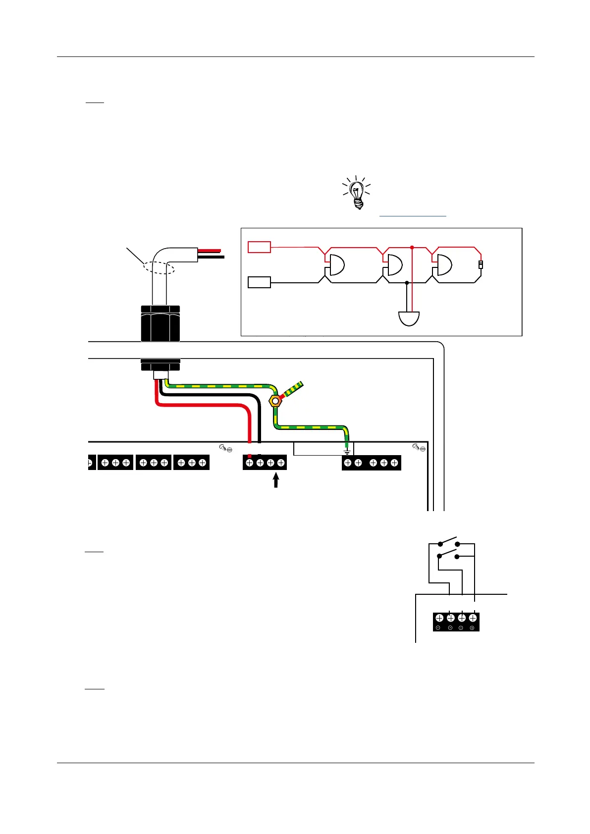
Conventional sounder circuit wiring
Two conventional sounder circuits are provided. See technical specification (page 47) for circuit limitations.
If a full complement of sounders are used, split them equally across both circuits. A 6k8 end of line (EOL)
resistor (provided) MUST be connected at the end of each sounder circuit to allow the wiring to be
monitored. If the sounder circuit is unused, the 6k8 resistor MUST still be fitted at the panel terminals.
Each sounder circuit should be connected to the Main Control PCB terminals marked: Sounder
Circuits 1+, 1- and 2+, 2-, as shown in Fig.6 below. Terminate earth screens at the panel’s base earth
distribution post, as shown in Fig.5, page 9.
Fig.6 : Typical conventional sounder circuit connection
ENGINEERING MANUAL • Approved Document No. DFU5010000 Rev 4 • Page 10 of 48
CAST XFP 16 ZONE ANALOGUE ADDRESSABLE FIRE ALARM PANEL
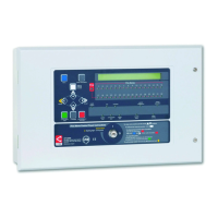
Input 1
Input 2
+24v I/P1 I/P2 0v
Auxiliary
Fig.7 : Typical auxiliary input wiring
Hint! C-TEC’s ActiV Sounder
range are compatible with this
fire alarm panel (available @
www.c-tec.com).
Relay output wiring
Four volt-free relay output connections are provided: a failsafe fault output* which switches for any
fault condition and three programmable auxiliary relay outputs. All four relays are capable of switching
1A @ 30Vd.c. and MUST NOT be used for directly switching Mains voltages.
* In the event of total de-energisation of the fire panel the fault relay will change state.
The three auxiliary outputs (Relays 1, 2 and 3) can be programmed using the panel’s PC programming
tools to operate as required but their default operations are:
Auxiliary input wiring
Two programmable auxiliary input connections (non-monitored) are
provided. These can be programmed using the panel’s PC programming
tools to operate as required. The wiring for each input should be
connected to the Main Control PCB terminal marked: Auxiliary, as
shown in Fig.7 right.
If applicable, i.e. in electrically noisy environments, input wiring
screens should be terminated at the panel’s base earth distribution
post, as detailed in Fig.5, page 9.