ENGINEERING MANUAL • Approved Document No. DFU5010000 Rev 4 • Page 47 of 48
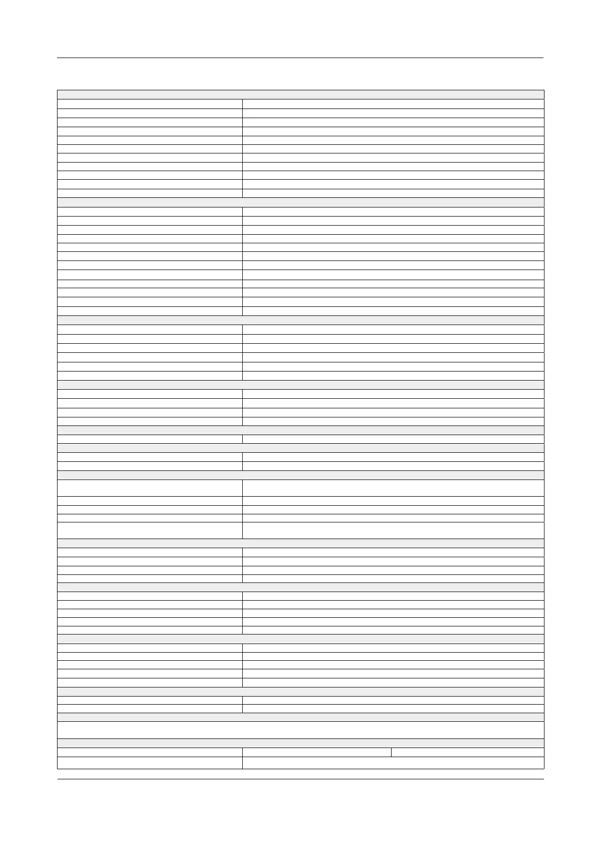
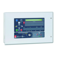
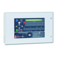
CAST XFP 16 ZONE ANALOGUE ADDRESSABLE FIRE ALARM PANEL
TECHNICAL SPECIFICATION
POWER SUPPLY
Mains supply (a.c.)
230V ∿ 50/60Hz. Rated current 0.35A r.m.s.
Internal power supply 18.7Vd.c. to 29.0Vd.c. (Ripple voltage 500mV p-p)
Maximum rated current 1.5A @ 230Va.c. (1.5A battery only with Mains off)
Current specification I max. a = 300mA; I max. b = 1.1A; I min. = 100mA
Maximum internal battery resistance Ri max. = 1.1Ω
Earth fault monitoring Yes (any conductor)
Mains supply & battery charger monitored for failure Yes
Batteries monitored for disconnection & failure Yes
Batteries protected against deep discharge Yes
Maximum battery size and type 2 x 12V, 0.8Ah to 3.2Ah VRLA batteries. Use YUCEL Y3.2-12 for LPCB approved systems.
Quiescent current 50mA (with Mains off)
LOOP DRIVER (PROGRAMMABLE & MONITORED)
Number of loop drivers 1
Communication protocol
CAST® (C-TEC Addressable System Technology)
Loop monitored for open and short circuit faults Yes
On-board loop isolators Yes
Auto-polling from each loop end & both ends (A & B) Yes
Maximum output current & voltage per loop 500mA (Voltage: 40V)
Max. number of addressable devices (detectors, MCPs) 255 CAST devices per loop
Device addressing options Devices automatically addressed by the panel, or manually addressed using CAPROG
Short-circuit isolator in every loop device Yes
Maximum loop cable length 1km
Number of programmable sounder groups 16
Number of programmable output sets 16
CONVENTIONAL SOUNDER CIRCUIT (PROGRAMMABLE & MONITORED)
Number of sounder circuits 2 (programmable, independent conventional circuits)
End of line (EOL) resistor value 6800 ohm, 5% tolerance, 0.25W
Line monitored for open and short circuit faults Yes
Each output fused at (max. sounder output current) 400mA. Protected by resettable overload circuit.
Output voltage 19.5V minimum; 28V maximum
Maximum line length per circuit 500m
AUXILIARY OUTPUTS (PROGRAMMABLE)
Relay type / Output Volt-free, single pole changeover / 1A, 30Vd.c. (maximum)
3 x auxiliary relays (Relay1, Relay2, Relay3) Programmed from cause and effects
1 x failsafe fault relay Active when no faults are present
‘+24Vd.c.’ Aux. power output 19.5V minimum, 28V maximum. Maximum current 100mA.
AUXILIARY INPUTS (PROGRAMMABLE, NON-MONITORED)
2 x auxiliary inputs (I/P1, I/P2) Connect to 0V to trigger, maximum input voltage 27Vd.c. (non-latching).
FUSES (to EN60127-2)
Primary fuse (F1) T 1A H 250V 20mm ceramic
(T=Time Delay, H=High Breaking Current)
Battery fuse (F2) 1.6A F 20mm ceramic (F=Fast Acting)
CONTROLS AND INDICATORS
Control buttons
Menu, More Information, Silence Internal Sounder, Control Panel Reset, Investigate,
Silence/Resound Sounders
Event scrolling and menu access buttons
(scroll up) 5
(1), (scroll down) 6 (3), Accept 4 (2), Escape 3 (4)
Liquid crystal display Two lines x 40 characters, backlit
Number of zonal LED indicators 16
Other LED indicators
(General) Fire, Supply Present, Test, Accessed, General Disablement, Phased Evacuation,
General Fault, Power Supply Fault, System Fault, Sounder Status, Delays Running.
PHYSICAL
Dimensions 380mm(W) x 235mm(H) x 90mm(D)
Weight / Construction 1.8kg (without batteries) / plastic detachable lid & plastic back box
IP Rating (to EN60529) IP30
Paint finish Light grey texture (RAL7035) epoxy paint
CABLING REQUIREMENTS
Type of cable Fire resistant screened cable, minimum size 1mm
2
Maximum loop cable length 1km
Connector blocks Fixed type, largest acceptable conductor size, 1.5mm
2
Maximum allowable loop impedance (each conductor) 20 ohm
Maximum cable capacitance .27µF
NETWORK (OPTIONAL)
Network connection Via XFP761 network driver card, one card fitted at each networked main panel
Network type
2-wire,
screened, enhanced fire-resistant cable ≥1 mm
2
, RS485 non-redundant network
Maximum number of main panels per network 8
Maximum no. of repeaters per non-networked main panel 8
Maximum cable length per network 1km (main panel network); 500m (repeater panel network)
PC/PRINTER INTERFACE
PC connection Via main PCB RS232 molex connector (lead supplied with XFP507 PC programming tools)
Printer connection Not available
OPERATING CONDITIONS
The enclosure is designed for indoor use only. The components are selected to operate within their specification when the environmental conditions
outside the enclosure comply with class 3k5 of IEC 721-3-3. Temperature range: -10
o
C to +40
o
C. Maximum humidity: 95% non condensing.
CERTIFICATES (Certificates and DOPs are available for download on C-TEC’s website)
LPCB Certificate Number: 176b LPCB Reference Number: 176b/26 CPR Certificate Number: 2831-CPR-F2522
Declaration of Performance: DOP0000071 Tested to: EN54-2:1997 + A1:2006 and EN54-4:1997 + A1:2002 + A2:2006
CAST XFP 1 Loop 16 Zone Panel (Part No. XFP501E/CA)