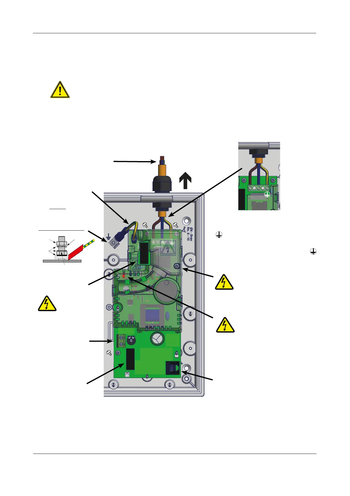
Connecting Mains to the Power Supply PCB
The panel’s PSU combines the functions of a power supply unit, battery charging unit, battery monitoring
unit and earth fault monitoring unit. It is positioned in the panel’s enclosure as shown in Fig.3 below.
CAUTION: DO NOT CONNECT MAINS TO THE POWER SUPPLY PCB UNTIL THE INSTALLATION IS
COMPLETE AND ALL RELEVANT PCBs ARE CORRECTLY FITTED IN THE PANEL.
ENGINEERING MANUAL • Approved Document No. DFU5010000 Rev 4 • Page 7 of 48
CAST XFP 16 ZONE ANALOGUE ADDRESSABLE FIRE ALARM PANEL
Fig.3 : Power Supply PCB layout and Mains connection (Full Protective Cover & Cable Cover shown fitted)
CONN2
BLK
-
RED+
VR1
F2
F1.6A
PL2
PL1
THIS
WAY UP
Incoming Mains Cable
This cable MUST be segregated from
other cables. Good quality cable
glands MUST always be fitted.
Primary Fuse (F1)
Exposed Live
parts under
fuse cover.
Isolate before
removal.
Battery Connector
(CONN2)
(Leads supplied in
the panel’s accessory
pack). See page 11 for
connection details.
Mains Input (CONN1)
L = Live (BROWN)
N = Neutral (BLUE)
= Earth (GREEN/YELLOW)
The incoming Mains earth wire MUST
be connected to the terminal marked
and NOT to the base earth distribution
post.
CONN1
NL
Cable cover
removed
PSU Earth Distribution Strap
This strap MUST be connected
to the spade on the
base earth
distribution
post before operation.
Battery Fuse (F2)
Connector Cable Socket (PL1)
Connect other end of lead to
the rear of Main Control PCB.
WHEN THE RED ‘HAZARDOUS
VOLTAGES PRESENT’ LED IS LIT
HAZARDOUS VOLTAGES ARE
PRESENT UNDER THE TWO COVERS.
ALLOW TO DISCHARGE FOR AT LEAST 5
MINUTES BEFORE REMOVAL & HANDLING.
nut
3 x plain
washer
Do not untighten lower nut
spring
washer
Base Earth Distribution Post
PSU Earth
Distribution
Strap
Exposed live parts under cable
cover. Isolate first, then remove
the small cable cover by loosening
its single retaining screw which is retained
in the cover. Only operate the PSU with
this cover securely fitted.