ENGINEERING MANUAL • Approved Document No. DFU5010000 Rev 4 • Page 11 of 48
CAST XFP 16 ZONE ANALOGUE ADDRESSABLE FIRE ALARM PANEL
GENERAL
FIRE
ZONE 1
ZONE 2
ZONE 3
ZONE 4
ZONE 5
ZONE 6
ZONE 7
ZONE 8
ZONE 9
ZONE 10
ZONE 11
ZONE12
ZONE 13
ZONE 14
ZONE 15
ZONE 16
D45
SUPPLY
PRESENT
TEST
ACCESSED
GENERAL
DISABLEMENT
PHASED
EVACUATION
GENERAL
FAULT
PSU
FAULT
SYSTEM
FAULT
SOUNDER
STATUS
DELAYS
RUNNING
Auxilliary
+24V I/P1 I/P2 0v
Relay 1
NC C NO
Relay 2
NC C NO
Relay 3
NC C NO
Fault
NC C NO
Sounder Circuits
+ 1 -
+ 2 -
Earth Fault Detect
Addressable Loop
+ A -
+ B -
REMOVING THIS CIRCUIT
BOARD EXPOSES HAZARDOUS
VOLTAGES - PLEASE REFER TO
INSTALLATION INSTRUCTIONS
WARNING
SENSITIVE TO STATIC
ELECTRICITY - OBSERVE
PRECAUTIONS BEFORE
HANDLING
CAUTION - RISK OF EXPLOSION IF
INCORRECT TYPE OF BATTERIES FITTED.
DISPOSE OF USED BATTERIES ACCORDING
TO THE MANUFACTURERS INSTRUCTIONS.
FOR OPERATIONAL DETAILS PLEASE
CONSULT THE MAINTENANCE MANUAL
Mute
Beeper
A Short
B Short
4
3
4
3
4
3
4
3
Fig.8 : Relay output detail
+–+–
+
I
+
+
I
–
+
–
Location of small
sized batteries
typically 1.2Ah
Location of medium
sized batteries
typically 2.1Ah
+
+
–
–
+
Take care to arrange
batteries so terminals
do not touch
Location of large
sized batteries
typically 3.0Ah
Connection of leads
to Power Supply PCB
Run the battery leads
(supplied) through slits
in the plastic ribs
R E D
BLACK
Tie wraps
Link wire
12V 12V 12V 12V 12V 12V
Power Supply
PCB
BAT1
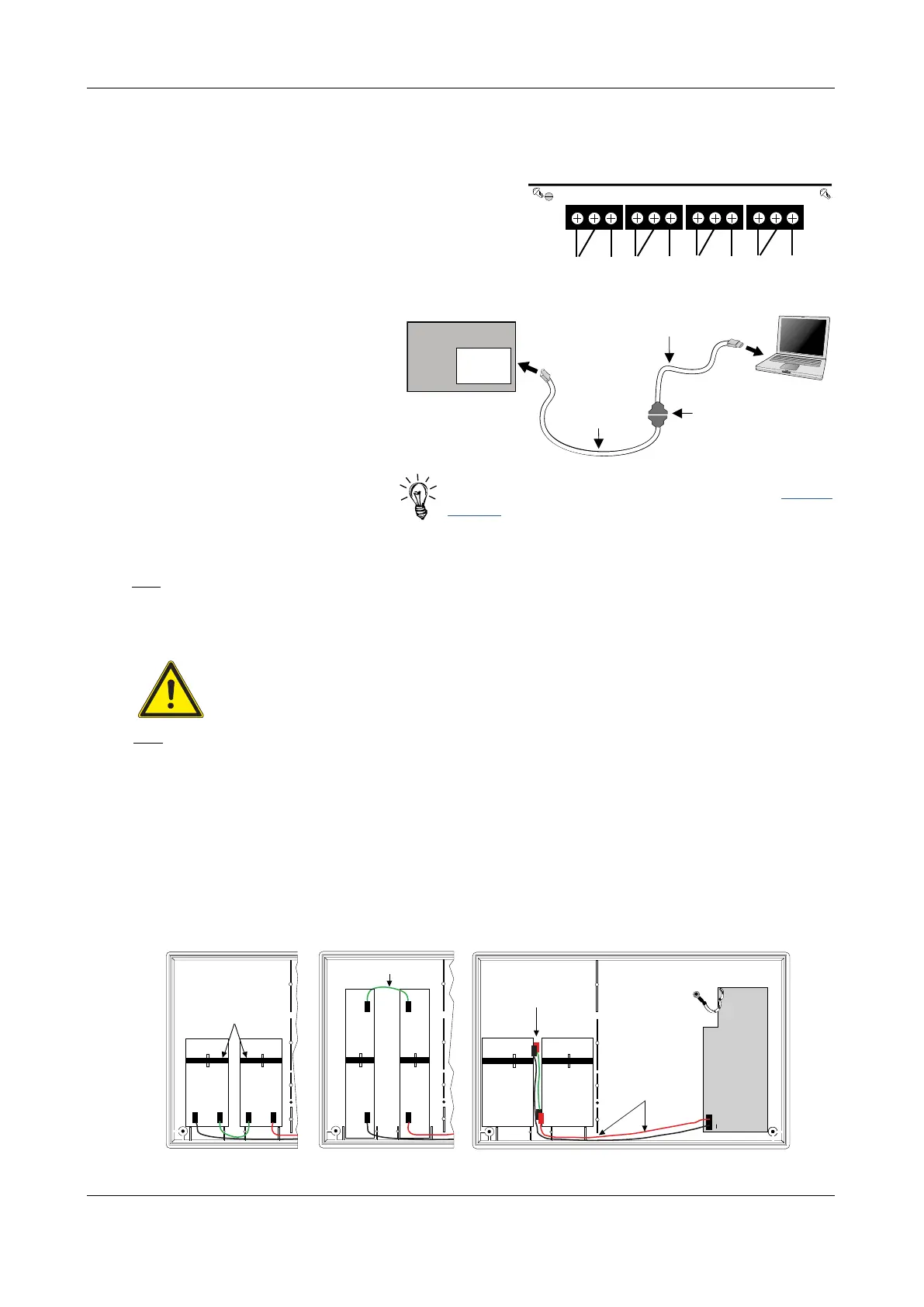
BF232
(USB-to-RS232 Convertor)
Control Panel
Main Control
PCB
SAF7070000
(Molex-to-RS232 Lead)
To USB
PC/Laptop
To PL5
Programming Connector
RS232 Connections
Fig.9 : Connecting a PC to the panel’s RS232 connector
Hint! Application Note 0001.0 (Setting up a Serial Comm
Port on a PC) is available in the Support Hub @ www.c-
tec.com to assist with setting up panel to PC comms.
Installing the standby battery supply
There is a risk of explosion if incorrect battery types or sizes are used. Always replace both
batteries and always dispose of used batteries in accordance with the battery manufacturers
instructions and local regulations. Batteries are heavy and can produce dangerously high
currents if shorted. Take care when handling and routing battery leads to avoid damage.
Two new, good quality and fully charged 12V valve regulated lead acid (VRLA) batteries are required
as the emergency stand-by power supply for the panel. The batteries should be connected in series and
located in the panel’s enclosure, as shown in Fig.10 below. Battery leads, link wire and cable ties are
provided in the panel’s accessory pack. Run the battery leads through the slits in the panel’s lower plastic
ribs and secure the batteries into position using the cable ties as shown.
The panel’s sophisticated battery monitoring unit protects the batteries against deep discharge by
activating a cut off circuit when the stand-by supply voltage reaches 21V approx. If batteries are not
fitted, are discharged or in poor condition, a PSU fault will show at the panel.
The capacity of the batteries used will depend upon the required stand-by time. To calculate the
batteries required for any given stand-by period, refer to the battery calculation guide on page 46.
Fig.10 : Battery location and connection details
Aux. 24V output
One fused 24Vd.c. output, rated at 100mA, is provided and can be used for supplying power to ancillary
fire alarm equipment.
Remote PC connection
A four-way RS232 molex connector
(PL5) is provided on the Main
Control PCB for the connection of
a Windows based PC / laptop. The
ONLY way to program this panel is
to use the panel’s PC programming
tools (Part No. XFP507).
The SAF7070000 lead supplied with
the tools should be used to connect
the panel and PC shown in Fig.9 right.
Note: A USB to RS232 connector is
also available (Pt. No. SAF8080000).
Relay 1 : Switches when any zone goes into fire, switches back when the panel is silenced.
Relay 2 : Switches when any zone goes into fire, switches back when the panel is reset.
Relay 3 : Has no default operation.
It is recommended that customers wire to the
normally closed (N/C) terminals on the fault relay,
as this is standard industry practice.
Fig.8 (right) shows how the outputs work.