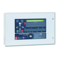
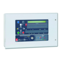
The XFP Networkable Analogue Addressable Fire Alarm Control Panel is a sophisticated fire alarm system designed for comprehensive fire detection and management. This user manual and log book, document number DFU2000510 Rev 1, provides detailed instructions for its operation, maintenance, and record-keeping, adhering to standards like BS5839-1.
Function Description
The XFP panel serves as the central control unit for a fire alarm system, capable of monitoring and managing fire conditions across multiple zones. It is an analogue addressable system, meaning each device connected to the panel has a unique address, allowing for precise identification of the location and type of event (fire, fault, pre-alarm, disablement, test). The panel is networkable, enabling it to integrate with other systems or panels for larger installations.
Key functions include:
- Fire Detection and Indication: Monitors smoke and heat detectors, manual call points, and other input devices for fire conditions. It provides visual (flashing red Fire indicator, flashing red Fire Zone indicators) and audible (pulsing internal sounder) alerts upon fire detection. The display shows the zone and name of the device in fire, and for multiple fires, lists the first and last zones with the total number of zones in fire.
- Pre-Alarm Conditions: Detects early signs of potential fire (e.g., increasing smoke levels) from detectors, providing an early warning before a full alarm. The internal sounder pulses, and the display shows details of the pre-alarm condition.
- Fault Monitoring: Identifies system failures such as detector faults, wiring faults, power supply issues, or system errors. Flashing yellow Fault indicators and a pulsing internal sounder alert users to faults, with detailed messages on the display.
- Output Control: Activates sounders, relays, and other output devices (e.g., auto-diallers, ancillary equipment) as programmed in response to fire conditions. Output delays can be programmed and monitored.
- System Disablement/Enablement: Allows authorised users to temporarily disable or enable specific parts of the system, including zones, sounder groups, output sets, auxiliary relays, individual loop devices, and the fault relay. This is useful for maintenance or to prevent nuisance alarms in specific areas.
- Testing Functions: Includes a lamp test to check the functionality of LED indicators and the display, and a walk test mode (indicated by a yellow Test light) for comprehensive system testing.
- Event Logging: Records all system events (fire, fault, disablement, test, time/date changes, access level entries) with timestamps, which can be viewed or printed from the panel.
- Alarm Counter: Tracks the total number of times the panel has been in a fire alarm condition since installation and since the last clear, providing a historical record.
Important Technical Specifications
While specific technical specifications like voltage, current draw, and loop capacity are not detailed in this user manual, the panel's functionality implies:
- Analogue Addressable Technology: Supports intelligent detectors and devices with unique addresses for precise event location.
- Networkable Capability: Suggests communication interfaces for connecting multiple panels or integration with building management systems.
- Multi-Zone Support: Available in 16-zone and 32-zone configurations, indicating scalability for different building sizes.
- Access Levels: Features three distinct access levels (General User, Authorised User, Engineer/Programming) with varying control capabilities, secured by entry codes or a keyswitch.
- Display: Liquid Crystal Display (LCD) provides detailed text messages for system status and events.
- Indicators: A comprehensive set of LED indicators for General Fire, Fire Zones (1-16 or 1-32), Supply Present, Test, Accessed, General Disablement, Phased Evacuation, General Fault, Power Supply Fault, System Fault, Sounder Status, and Delays Running.
- Controls: Push buttons for More Information, Scroll Up/Down, Accept, Escape, Menu, Silence Internal Sounder, Control Panel Reset, Silence/Resound Sounders, and Investigate. A keyswitch provides instant access to Access Level 2.
Usage Features
The XFP panel is designed for user-friendliness while maintaining robust security and control.
- Clear Status Indication: The LCD and LED indicators provide immediate and clear visual feedback on the system's status, including normal operation, fire, pre-alarm, and various fault conditions.
- Intuitive Navigation: Menu-driven interface with scroll, accept, and escape buttons allows for easy navigation through system options and event logs.
- Multi-Level Access Control: Ensures that only authorised personnel can perform critical operations, preventing accidental or malicious changes to the system. Access Level 1 (general user) allows viewing events, testing lamps, and checking the alarm counter. Access Level 2 (authorised user) adds controls for silencing/resounding sounders, resetting the panel, changing time/date, managing disablements, and accessing event logs. Access Level 3 is reserved for engineers for programming and configuration.
- Investigate Timer Function: For authorised users, an "Investigate" button initiates a timer, allowing investigation of a potential alarm before full sounder activation, if enabled by an engineer. This helps reduce false alarms.
- Comprehensive Event Logging: The panel automatically logs all significant events, providing a detailed history for analysis and compliance. This log can be printed or displayed.
- Alarm Counter: Provides a quick overview of the system's alarm history, useful for identifying patterns or frequent false alarms.
- Output Delays: Programmable delays for outputs allow for controlled evacuation procedures or integration with other building systems.
Maintenance Features
The manual emphasizes the importance of regular maintenance and provides tools to facilitate it.
- Fire Alarm Log Book: An integral part of the manual (pages 21-26) for recording all system events, tests, fire drills, false alarms, faults, and maintenance work. This is crucial for compliance with standards like BS5839-1.
- System Set-Up Data Chart: (page 20) Provides a record of how each zone is set up for normal operation, dependencies, investigate facility, and output delays. This chart is to be completed by the system engineer.
- Installation and Commissioning Certificates: (pages 27-28) Essential documents to be completed by competent persons, certifying that the system has been installed and commissioned in accordance with relevant standards (e.g., BS5839-1).
- Fault Reporting and Rectification: The panel's detailed fault messages assist in quickly identifying and rectifying issues. The log book facilitates recording faults and tracking their resolution.
- Regular Servicing: The manual stresses the importance of regular servicing by a competent organisation to ensure continuous operation and compliance.
- Expendable Component Replacement Periods: A section in the log book for listing replacement schedules for components, aiding proactive maintenance.
- Disablement Management: The ability to disable specific parts of the system during maintenance prevents unwanted activations and allows for isolated testing.
- Lamp Test: A quick and easy way to verify the functionality of the panel's visual indicators.
Overall, the XFP Networkable Analogue Addressable Fire Alarm Control Panel is a robust, feature-rich system designed for reliable fire detection, clear communication of events, and comprehensive management, supported by detailed documentation for installation, operation, and maintenance.