BASIC OVERVIEW & KEY FEATURES
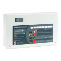
The fire alarm panel is designed for use with fire and security systems and includes the following features:
• Two, four or eight AlarmSense™ zone circuits (dependent on the model purchased);
The design of the panel’s zone circuits allows AlarmSense™ detectors, manual call points and sounders to be
fitted across the same two zone wires (conventional panels typically use four wires, two for the detectors/
call points and two for the sounders). In many installations it is more cost-effective to install a two wire
system rather than a conventional four wire system due to savings in cabling and installation labour.
It should be noted that no other type of device is compatible with the zone circuits except AlarmSense™
detectors, AlarmSense™ manual call points and AlarmSense™ sounders.
• Four conventional sounder circuits (designed for use with non-AlarmSense™ sounders);
• A flush or surface mountable plastic lid and enclosure;
• A wide range of secure user functions (as detailed in the separate User Manual/Log Book) including the
ability to disable/enable a large number of system functions, as specified in EN54;
• Keypad and keyswitch entry to authorised user controls (access level 2);
• A wide range of engineering functions, including:
Selectable zone delay facility
Non-latching zones facility. Note: This function is non-compliant with EN54-2.
Coincidence (double-knock) facility. Note: This function is non-compliant with EN54-2.
Zone test facility
Programming silenced sounders to resound, or not resound, when a new zone is in alarm
Programming zone circuits to have sounders fitted or not fitted
Comprehensive fault diagnostic facilities
• The following optional EN54 Part 2 features:
Output(s) to fire alarm devices {Clause 7.8}. Four conventional sounder circuits are provided to drive
external alarm sounders.
Delays to outputs {Clause 7.11}. A delay facility (selectable on a zone by zone basis) is provided to delay
the alarm sounders, remote fire and/or auxiliary outputs.
Test condition {Clause 10.0}. A zone test facility is provided.
• The following features that are not required by EN54 Part 2:
Reset output (RESET) open collector output which provides a signal to reset any part of the fire alarm
system (if required) whilst the panel is being reset.
Remote output (REM) open collector output and Auxiliary fire relay output (AUX) which provide a signal
to any part of the fire alarm system that needs to be activated during a fire alarm condition.
Two (non-latching) auxiliary input connections; ‘class change’ and ‘alert’.
• A Fault relay output (FAULT).
Important Note: It is possible for the panel to determine if an AlarmSense™ manual call point, or an
AlarmSense™ detector has triggered a zone into alarm. This allows the system to be optionally set up so
that, if required, the activation of a manual call point will override delays and coincidence.
INSTALLATION & MAINTENANCE MANUAL • Approved Document No. DFU7002020 Rev 4 • Page 3 of 24
LPCB APPROVED CFP ALARMSENSE 2/4/8 ZONE FIRE ALARM PANEL
EN54 COMPLIANCE STATEMENT
This fire alarm panel is fully compliant with the requirements of EN54 Part 2 (Fire
detection and fire alarm systems, control and indicating equipment) and EN54 Part 4 (Fire
detection and fire alarm systems, power supply equipment) and is certified as meeting
these standards by the Loss Prevention Certification Board (LPCB) - unless stated.
Please note, some of the engineering functions provided on the panel go
beyond the scope of EN54 Part 2. A caution symbol (left) is used to indicate
where such a function is non-compliant with EN54-2.
DO NOT affix the LPCB approval label (supplied) to the front of the panel if it
has been configured to operate in a way that would make it non-compliant
with the requirements of EN54-2.
Read these instructions thoroughly before installation and operation
General Warning Sign
Danger Electrical Hazard
Symbols
13
2831-CPR-F0386

 Loading...