06
44
CROSSBOW CS / POWERDRIVE CS
In order to replace your control system’s flying lines, you must first remove the existing flying lines from the leader lines. You
may then attach new flying lines to the current leader lines, assuming the leader lines are in an acceptable condition.
Connect Your New Flying Lines to the Leader Lines
• Lay your Control System face up on the ground ap-
proximately 30 meters away from a post or tree to which
you will be attaching your lines in order to check that the
lengths are even (see Step 1.2).
• Unwind and lay out the color-coded FLYING LINES between
the post and the control bar. You will have two sets of
lines-the front (or inside) DE-POWER LINES and the back
(or outside) STEERING LINES
• Make sure your flying lines are not twisted or crossed.
Do this by walking down your lines, separating them from
each other. Once you have them separated, lay them down
in this order from left to right while looking from your
control bar toward the end of the lines: yellow steering line,
yellow-sheathed white de-power line, black-sheathed white
de-power line, black steering line.
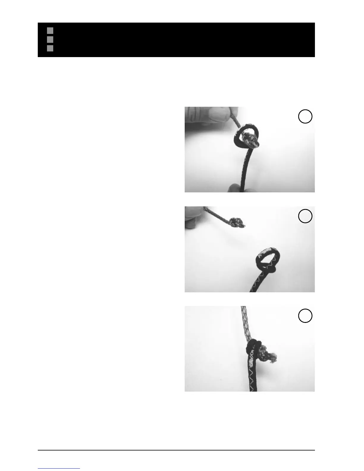
• You will connect the steering lines to the rear leader with
a “larks head to knot” connection. You must first create a
larks head loop with each of the flying lines. {IMG}You will
then place the yellow-sheathed loop over the knot on the
left leader line. Pull the connection tight to secure. Then
place the black-sheathed loop over the knot on the right
leader line. Pull the connection tight to secure
• Pull the connection tight for a secure connection (Fig. 3).
• In order to replace your center lines, you must first create
a larks head loop with each de-power flying line. You will
then place the yellow-sheathed loop over the knot on the
left leader line on the Centerline Adjustment Strap (CAS).
Pull the connection tight to secure. Then place the black-
sheathed loop over the knot on the right leader line on the
CAS. Pull the connection tight to secure
• Your flying lines are now connected to your leader lines,
and you are ready to make sure that all of your lines are
even.
S ET UP
REPLACING YOUR FLYING LINES - CROSSBOW CS / POWER DRIVE CS
1
2
3