Tap RFID card area prompt light
The four square corners of the RFID card tap area are highlighted
to show where the RFID card should be active
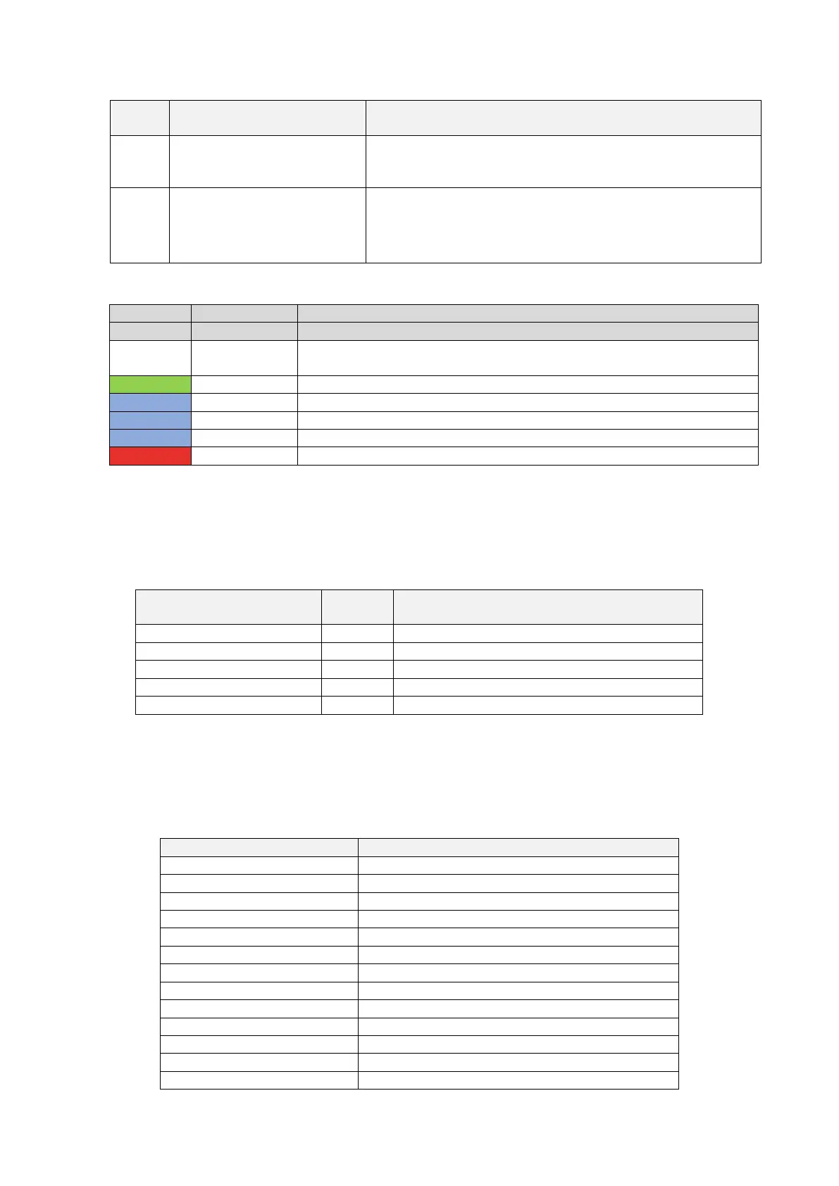
A LED belt is placed all around the charger and assumes different
colours to indicate the current status (see table below)
Power on self-test: the charger is switching on and performing the power on
tests
Stand-By mode: the charger is on, available for charging
Pause during the charging process
Charging mode setup: the charger is preparing to start the charging process
Charging mode: the charging process is ongoing
Error mode: errors are detected by the internal protections
7.1.2 Digital character display (AREA1)
The following table shows the format of the information presented by the frontal display:
Display string format
(Letter “c” = single character)
Where ccc = Input supply voltage value (V)
Where cc.c = Charging current value (A)
Where cc.c = Input supply voltage frequency (Hz)
Where cc.c = Output power (kWH)
Where ccc = Charging process duration (Min)
These data are presented in rotation on the display.
In case of errors/faults/abnormal behaviours, the display can show the following error message
codes. The following table explains the meaning of each error code:
Meter communication fault
Relay over-temperature fault
Electronic lock abnormal fault
Plug holder over-temperature fault
Fan fault (the fan is blocked)