Mod. A1735-A1835-A1735B-A1835B HV Boards
Channels
Out 0
Out 1
Out 2
Out 3
Out 4
Out 5
Out 6
Out 7
Out 8
Out 9
Out 10
Out 11
Channels
Channels
Channels
Controller
Channels
Channels
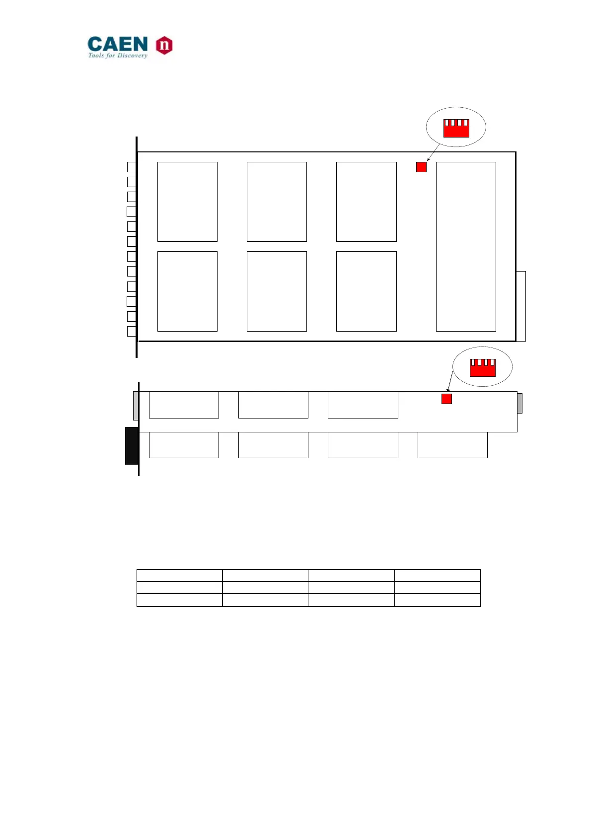
Dip Switch
(side view)
T A B C
4
3 2
1
A)
B)
Dip Switch
T A B C
4 3
2
1
Channels
Channels
Channels
Channels
Channels
Channels
Channels
Fig. 3.1 – A) Mod. A1735 - A 1835 side view; B) Mod. A1735B - A 1835B top view
In order to select the desired Full Scale Range (FSR) the dip-switches must be set as
illustrated in the following table.
Table 3.1 - Full scale range settings
Full scale range selection must be performed before inserting the board into the crate.