LMU Controller
© Safe Fleet | May 2022 | All rights reserved | Part #: 700-1284 R1 p. 10
LMU Controller LEDs
8. Run the harness cabling and the GPS and Cellular cabling to the intended LMU Controller location.
9. Connect the GPS and Cellular connectors to the LMU Controller.
10. Connect the 20 pin harness to the LMU Controller.
11. Tie off unused wires from harness.
LMU Controller LEDs
Operation Status
Once the 20 pin harness is connected to the LMU Controller, this will have power.
The LMU Controller is congured to provide vehicle tracking and live video streaming information to AVL GPS Tracking
application (a.k.a. vMax Live+) users.
LEDs on the LMU Controller indicate operation status and display operation mode conditions as described below.
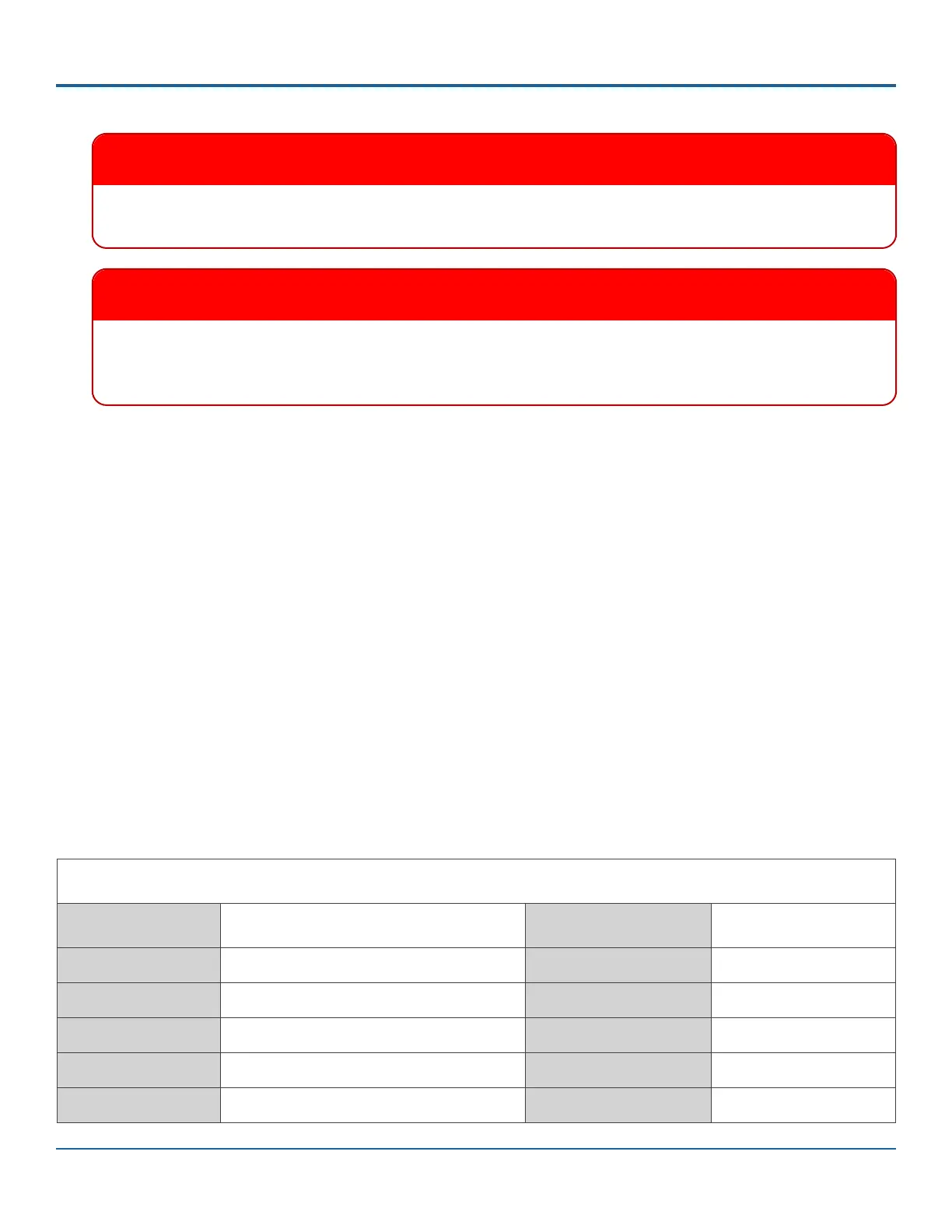
LED Status Indicators
Comm LED - Orange Condition GPS LED - Green Condition
Off Modem Off Off GPS Off
Slow Blinking Comm On - Searching Slow Blinking GPS On
Fast Blinking Network Available Fast Blinking GPS Time Sync
Fast Blink to Solid Registered - no Inbound Acknowledgment Solid GPS Fix
Solid Registered - Inbound Acknowledgment
IMPORTANT
If you are replacing an LMU27, you can keep the same harnesses as long as the length allows the new LMU to
be installed on the dash with its label facing the sky. Otherwise you can use the new harness that comes with
the product package.
IMPORTANT
If the DVR has a GPS4 unit installed, the GPS4 unit can be removed. The LMU Controller replaces GPS4
functionality on the DVR.
(Install LMU Controller continued)
 Loading...