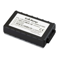
LMU Controller
© Safe Fleet | May 2022 | All rights reserved | Part #: 700-1284 R1 p. 6
Installation
Install LMU Controller
1. Select an LMU Controller modem installation location that meets the following requirements:
CAUTION: Installation Requirements
• The LMU Controller must be installed within the range of the cables distance.
• Install within the vehicle, close to the DVR if possible.
• Install where LEDs can be seen if necessary.
• Install in the front of the vehicle.
• Route the wiring and cables away from sharp edges that might damage the insulation.
• Avoid sharp bends in the cable.
Installation Requirements
Location The LMU contains a built-in GPS antenna, which can be obstructed by metal objects. The best place
to mount the LMU for optimal GPS reception is on top of the front dash panel, with the label facing
out towards the sky.
Choose a dry location with easy access to the electrical panel and cable connections to mount the
LMU Controller.
Install the LMU Controller away from any place where tampering with the device or cable connections
may occur.
Surface Do not mount the LMU Controller to a plastic panel or other surface that is subject to constant
vibration.
Clearance Allow sufcient clearance of at least six (6) inches in front of the LMU Controller and two (2) inches
on each side for easy access and removal of cable connectors and ports.
Allow sufcient clearance behind the LMU Controller for power cables.
Harnesses Provide enough slack on the power cable to prevent any force from being exerted on the connectors.
A single 4-inch diameter loop is sufcient.
2. Using the supplied alcohol wipe pad, clean the vehicle surface where the LMU Controller will be installed.
3. Peel the protective cover from the velcro backing on the LMU Controller. Be careful not to touch or allow any foreign
material to come in contact with the exposed adhesive.
4. Attach the LMU Controller to the vehicle.
5. Clip the 1x2 Microt connector from the end of the alarm button extension cable.
6. Connect the alarm button’s red and black wires to the extension cable’s red and black wires with the supplied crimps.
7. Connect all power, alarm, GPS, and Stop Arm cabling to the LMU Controller 20 pin harness, and if you are connecting
the LMU Controller to a DVR, connect the AUX 1 from the LMU Controller harness to the supplied adaptor cable,
using the appropriate diagram (presented in the following pages) to guide you through the process.

 Loading...