LMU Controller
© Safe Fleet | May 2022 | All rights reserved | Part #: 700-1284 R1 p. 7
Installation
DH Series Users
If you have a DH video recorder, which does not have 2x2 GPS socket, proceed to the following pages to learn how to
connect the LMU to your device. You'll nd two different options. Notice that this does not apply to DH4C.
LMU Controller Connection for Video Recorders with 2x2 pin GPS Socket
The connection between the LMU Controller and the video recorder is different depending on which type of device you have
installed in the vehicle. The following diagrams will help you set up three different systems with different components:
Aux 1
Cable Harness
and Connector
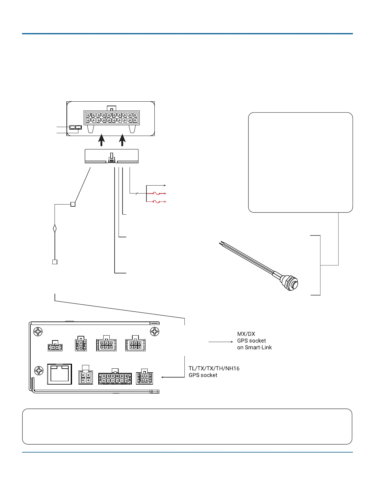
LMU Controller Connections
Typical System Setup for DVR with 2x2 GPS Socket
LMU
to GPS
Adaptor
Cable
Power Harness
060-1018
060-1012
GPS4-CBL
(20ft / 6.1m)
Red, black, white wires
LMU Controller VLP-LMU26M
LMU Controller
Harness LED end
Comm LED
GPS LED
1x5 Microfit
connector
2x2 Microfit
connector
To
DVR
options
Pin 1
Pin 11
Pin 11
Pin 10Pin 10
Pin 20Pin 20
GPS4 Extension
Cable
ETHERNET POWER
SIGNALS
GPS
CAM2CAM1
CONTROL
ALARM
Battery Negative (black)
Vehicle + 12/24V (red)
Ignition (white)
3 wires
3A
3A
Black wire from pin 16 to black on
extension cable
Pin 16 - Alarm Button
(black wire, active low)
Pin 3 - Stop Arm
(blue wire, active high)
Orange wire from pin 12 to red on
extension cable
Pin 12 - Alarm Button
(orange wire, active low)
Alarm Button 060-0061
Alarm Button / Extension Cable
To connect the extension cable, use
supplied butt connectors (2x) to
connect the alarm button ying leads
to the extension harness ying leads
(Red to Red, Black to Black). Cut the
2x1 Molex connector off the extension
cable and use supplied butt connec-
tors (2x) to connect the extension
harness red wire to the LMU harness
pin 12, orange wire. Then, connect the
extension harness black wire to the
LMU harness pin 16, black wire.
 Loading...