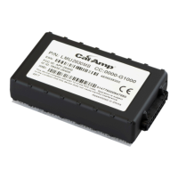
The LMU Controller, specifically the LMU 2630MB (VLP-LMUE1Y1) model, is a location messaging unit designed for vehicle tracking and live video streaming. It integrates with AVL GPS Tracking applications, such as vMax Live+ 5.0, to provide real-time location data and other vehicle activity information to users. This device operates across various cellular networks, including AT&T, T-Mobile, Verizon, Telus, Bell, and Rogers, ensuring broad coverage for tracking purposes.
Function Description
The primary function of the LMU Controller is to act as a telematics device, collecting and transmitting vehicle data. It features a built-in GPS antenna for acquiring location information, which is then relayed over cellular networks. This data enables users to monitor vehicle positions, routes, and other operational parameters through a centralized tracking application. The LMU Controller is capable of providing both vehicle tracking and live video streaming information, making it a versatile tool for fleet management and security.
When installed, the LMU Controller works by continuously acquiring GPS signals to determine the vehicle's precise location. This location data, along with other relevant vehicle activity, is then transmitted via the cellular modem to the vMax Live+ application. The device is designed to be integrated into a vehicle's electrical system, drawing power from the vehicle's battery. It includes a power harness with fuses for protection and proper connection.
For enhanced functionality, the LMU Controller can be connected to other vehicle systems, such as a Digital Video Recorder (DVR). When integrated with a DVR, the LMU Controller can provide GPS functionality to the DVR, replacing the need for a separate GPS unit (like a GPS4 unit) if the DVR has an older firmware version or lacks integrated GPS. This integration allows for synchronized location data with video recordings, offering a comprehensive view of vehicle operations. The LMU Controller supports various connection configurations, depending on whether it's installed standalone or with different types of DVRs, including those with or without 2x2 pin GPS sockets.
The device also supports an alarm button input, allowing drivers to trigger an alert in emergency situations. This alarm signal is transmitted through the LMU Controller to the tracking application, notifying fleet managers or security personnel of a potential incident. The alarm button connects to the LMU harness, and its activation status can be monitored.
The LMU Controller is configured to have a power off delay, typically 15 minutes after ignition off. This feature is designed to allow for cellular transmission delays, ensuring that all vehicle activity, especially after the vehicle reaches its destination and powers down, is communicated to the tracking system. This delay helps in capturing complete trip data and preventing data loss during vehicle shutdown.
Usage Features
The LMU Controller is designed for professional installation within a vehicle. Its compact size allows for flexible mounting, with specific recommendations to ensure optimal performance. The ideal mounting location is on top of the front dash panel, with the label facing upwards towards the sky, to maximize GPS reception. It should be installed in a dry location with easy access to electrical and cable connections, yet away from potential tampering. Sufficient clearance around the device is recommended for proper cable management and access to connectors.
The installation process involves connecting the LMU Controller to the vehicle's power supply, the alarm button, and optionally to a DVR or other expansion harnesses. The power harness includes connections for battery negative, vehicle positive (12/24V), and ignition. The device's harness also provides inputs for a stop arm (active high) and the alarm button (active low).
Once installed and powered, the LMU Controller provides visual feedback through two LEDs: a Comm LED (orange) and a GPS LED (green). These LEDs indicate the device's operational status, allowing installers and users to quickly assess its functionality.
- Comm LED (Orange):
- Off: Modem Off
- Slow Blinking: Comm On - Searching (for cellular network)
- Fast Blinking: Network Available
- Fast Blink to Solid: Registered - no Inbound Acknowledgment
- Solid: Registered - Inbound Acknowledgment
- GPS LED (Green):
- Off: GPS Off
- Slow Blinking: GPS On (searching for satellites)
- Fast Blinking: GPS Time Sync
- Solid: GPS Fix (location acquired)
These LED indicators are crucial for troubleshooting and verifying proper operation after installation. For instance, a solid GPS LED indicates that the device has acquired a GPS fix, while a solid orange Comm LED indicates successful registration with the cellular network and acknowledgment from the tracking server.
Provisioning the LMU Controller is a key step after physical installation. This involves configuring the device within the AVL GPS Tracking application (vMax Live+). The provisioning process ensures that the LMU Controller is correctly linked to the user's account and starts transmitting data as expected. This is typically done through an online tutorial provided by Safe Fleet.
Maintenance Features
While the LMU Controller itself is a robust device designed for continuous operation, its maintenance primarily revolves around ensuring proper installation and connectivity. Regular checks of the cabling connections are important, especially if the device fails to start or is not detected by the tracking application. Loose or improperly connected power cables can prevent the unit from functioning.
In cases where the LMU Controller is not detected by the tracking application, or if GPS data is not being received, troubleshooting steps include moving the vehicle out of a garage or covered area to ensure clear line of sight to GPS satellites. The built-in GPS antenna requires an unobstructed view of the sky for optimal reception. If cellular connection issues persist, contacting Safe Fleet Technical Support is recommended, as this may indicate network-related problems or device configuration issues that require expert intervention.
The device is designed to be durable, but its operational environment should be considered. It is recommended not to mount the LMU Controller to surfaces subject to constant vibration, such as plastic panels, to prevent potential damage over time. Routing wiring and cables away from sharp edges and avoiding sharp bends helps protect the insulation and ensures long-term reliability of the connections.
The LMU Controller is a sealed unit, and there are no user-serviceable parts inside. Any internal issues or repairs would typically require professional service or replacement. The product comes with a warranty, and complete details are available from the manufacturer, which outlines the terms for repair or replacement in case of defects. For product information and documentation, users can access the Safe Fleet community portal, provided they have the necessary access credentials. Technical support is available via phone and email for any operational or troubleshooting assistance.