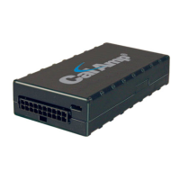
The CalAmp Location and Messaging Unit-TTU-2830™ (TTU-2830™) is a mobile device designed for fleet management systems. It resides in private, commercial, or government vehicles, providing location information and supporting inputs/outputs to monitor and react to the vehicular environment and/or driver actions. The TTU-2830™ is a single-box enclosure that integrates a processor, a GPS receiver, a wireless data modem, and a vehicle-rated power supply.
The primary function of the TTU-2830™ within a fleet management system is to enable remote contact with a vehicle, determine its location or status, and perform meaningful actions with that information. This includes displaying vehicle location on a map, performing address look-ups, providing real-time driving directions, updating vehicle ETAs, monitoring vehicle and driver status, or dispatching the vehicle for its next pick-up. The device delivers location information when and where it is needed, working in conjunction with a wireless data network and backend mapping/reporting software (e.g., from Actsoft). The backend software parses and presents data from the TTU-2830™, allowing for display of location data, presentation of historic information in report/chart formats, and requesting location updates.
Important Technical Specifications:
Size and Weight:
- Dimensions: 4.3" long x 3.2" wide x 1.6" high (110 mm long x 80 mm wide x 40 mm high)
- Weight: 9.6 oz (272 g)
Environmental Specifications:
The TTU-2830™ is designed to operate in typical fleet vehicle environments, with wide temperature extremes, voltage transients, and potential interference. It has been subjected to SAE standard tests (J1455, J1113 Parts 2, 12, 21, 41) for temperature, shock, vibration, and EMI/EMC, and is considered a "Functional Status Class B, Performance Region II" system requiring Threat Level 3 Testing.
- Operating Temperature: -30° C to 70° C
- Storage Temperature: -40° C to 85° C (20° C to 50° C for internal battery power)
- Humidity: 0% to 95% relative humidity, non-condensing
- Shock and Vibration: SAE J1455 Compliant, Mil Standard 202G and 810F Compliant
- Electromagnetic Compatibility (EMC/EMI): SAE J1113 Parts 2, 12, 21, 41 Compliant, FCC Part 15B Compliant, Industry Canada Compliant
Power Specifications:
- Operating Voltage Range: 9-32VDC
- Back-up Battery: 5.2Ah mAh (up to 6 months at 1 message per day with deep sleep enabled)
- Charge Time: 4 Hours
- Power Consumption:
- Active Standby: < 70mA at 12VDC
- Radio Active Sleep: < TBD at 12VDC
- Deep Sleep: < 2mA at 12VDC
GPS Receiver:
- Channels: 50 channel WAAS capable GPS Receiver
- Accuracy: 2.5m CEP (with SA off)
- Tracking Sensitivity: -162 dBm
Communications (Comm):
- Data Support: SMS, GPRS, CDMA 1xRTT or HSPA packet data
- GSM/GPRS: Quad-Band (850/900/1800/1900 MHz)
- Output Power: Class 4 (2 Watts) 850/900 bands, Class 1 (1 Watt) 1800/1900 bands
- CDMA: Dual-Band (800/1900 MHz)
- Output Power: 800: +24dBm, 1900: +24dBm
- HSPA/UMTS: Dual-Band (900/2100 MHz (bands VIII, I) or 850/1900 MHz (bands V, II))
- 3GPP Release: 6
- Upload Speed: 5.6 Mbps
- Download Speed: 7.2 Mbps
- GSM/GPRS Fallback: 850/900/1800/1900 quad-band
- GPRS Class: 12, EDGE MCS1-MCS9
- Compliance: RoHS Compliant
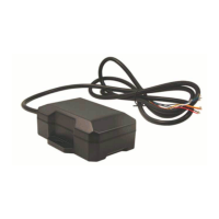
Primary Connector (8 22AWG leads for power and I/O):
- Wire 1 (Black): GND (Ground) - Output
- Wire 2 (Red): Vcc (Primary Power) - Input
- Wire 3 (White): IN-0 (Input 0 - Ignition) - Input
- Wire 4 (Blue): IN-1 (Input 1 – Digital Input) - Input
- Wire 5 (Orange): IN-2 (Input 2 – Digital Input) - Input
- Wire 6 (Green): OUT-0 (Output 0 - Starter Disable Relay Driver) - Output
- Wire 7 (Brown): OUT-1 (Output 1 - Digital Output) - Output
- Wire 8 (Yellow): OUT-2 (Output 2 - Digital Output) - Output
- Wire 9 (Green/Black): SER_OUT (Serial Output) - Output
- Wire 10 (Blue/Black): SER_IN (Serial Input) - Input
I/O Descriptions:
- Digital Inputs:
- Input 0: Ignition Sense (Always biased low).
- Input 1: Generic Digital Input (high or low bias per S-158).
- Input 2: Generic Digital Input (high or low bias per S-158).
- Input 3 & 4: Not Available.
- Input 5: Motion Sensor (low = no motion, high = motion).
- Input 6: Power Switch State (low = external power, high = internal battery).
- Input 7: Battery Voltage Critical Sensor (low = VBatt ok, high = VBatt low; 3500mV threshold).
- Input 8: High Temperature Sensor (low = below Temp Threshold, high = above Temp threshold; Temp Threshold = 300).
- Analog to Digital Inputs:
- A/D 0: External Power Supply Monitor
- A/D 1: Generic External Analog to Digital Input
- A/D 2: GPS Antenna Monitor
- A/D 3: uP Temperature
- A/D 4: uP Voltage
- A/D 5: Battery Voltage
- A/D 6: Temperature Sensor
- A/D 7: Vcc Sys
- Outputs:
- Output 0: Standard Open Collector Relay Output
- Output 1: Standard Open Collector Relay Output
- Output 2: Standard Open Collector Relay Output
- Output 3: Not Available
- Output 4: Power Supply Switch (cleared = switch to external power, set = switch to internal power)
- Output 5: Enable/Disable Battery charging (cleared = enable battery charging, set = disable battery charging)
Usage Features:
- Motion Sensor Input: The TTU-2830™ includes an internal motion sensor. If motion is detected for at least 30 consecutive seconds, the device will track at a 5-minute interval for approximately 350 messages.
- Power State Input: The device can detect whether it is operating on external power (Low state) or its internal back-up battery (High state).
- Battery Voltage Critical Input: A built-in low battery threshold of 3500mV is tied to a discreet input. If the battery reaches this limit, a Low Battery event is sent to Actsoft systems.
- Ignition and Inputs: The TTU-2830™ provides up to 3 external inputs, protected from typical vehicle transients. These can be directly connected to vehicle-level logical inputs from 4V up to the vehicle power input level (typically 12VDC). Input impedance is approximately 10kΩ. One input is dedicated to ignition status for flexible power management. The other two inputs can sense vehicle inputs like cooling unit operation, a "Panic" switch, or taxi meter status. The ignition input is pulled to ground through 10kΩ resistance. Other inputs can be normally High (pulled to +12V through 10kΩ) or Low (pulled to ground through 10kΩ).
- Status LEDs: The TTU-2830™ has two Status LEDs: one for GPS (Green) and one for COMM (Orange), indicating service status through blink patterns.
- Comm LED (Orange) Definitions:
- Off: Modem Off
- Slow Blinking: Comm On - Searching
- Fast Blinking: Network Available
- Alternates from Solid to Fast Blink every 1s: Registered but no Inbound Acknowledgement
- Solid: Registered and Received Inbound Acknowledgement
- GPS LED (Green) Definitions:
- Off: GPS Off
- Blinking: GPS On Slow
- Fast Blinking: GPS Time Sync
- Solid: GPS Fix
Maintenance Features:
- Installation Planning: Proper installation is crucial for optimal performance. Installers should be familiar with GPS and cellular device installations in vehicles. Key steps include verifying power, ground, and ignition sources with a multi-meter, and planning component placement (LMU, antennas, peripherals) to avoid bent or constricted cables and direct exposure to elements (sun, heat, rain, moisture). Violating environmental specifications voids the warranty.
- Antenna Placement: For combination and internal antennas, GPS performance is prioritized over Comm performance due to lower signal strengths. The LMU should have a clear view of the sky, with the GPS antenna having minimal obstructions (ideally near the center of the roof, or under front/rear windshields for covert installs).
- Protection from Heat: Avoid placing the LMU near heater vents, hot engine components, or in direct sunlight to prevent exposure to unusually warm temperatures, which could exceed environmental specifications.
- Visibility of Diagnostic LEDs: Install the LMU where its Status LEDs can be easily seen. These LEDs provide valuable diagnostic information for troubleshooting. If issues arise, the LED patterns can be communicated to CalAmp customer support.
- Moisture and Weather Protection: The LMU must be located in a dry area, protected from moisture and water. Avoid locations like below cup holders or where rain could splash in when a door is opened.
- Preventing Accidental/Unauthorized Modification: To prevent tampering, measures like tamper-proof sealant or PEG Script to detect power loss or GPS antenna disconnections can be used.
- Battery Disposal: Proper disposal of batteries in CalAmp products is required. Used or replaced batteries, or units containing them, should not be thrown in regular trash. Local waste management facilities should be consulted for disposal instructions.
- Electrical Over-Stress (EOS) Protection: The GPS receiver can be damaged by excessive RF levels. During storage and shipping, TTU-2830™ GPS Antennas should be kept at least four inches apart from any active TTU-2830™ GSM Antenna or other active high-power RF transmitters (>1 Watt) to prevent damage if one unit is in transmit mode.