© Caleffi 08301_iSolar Plus 24V.monus.indd
| 4
VBus
®
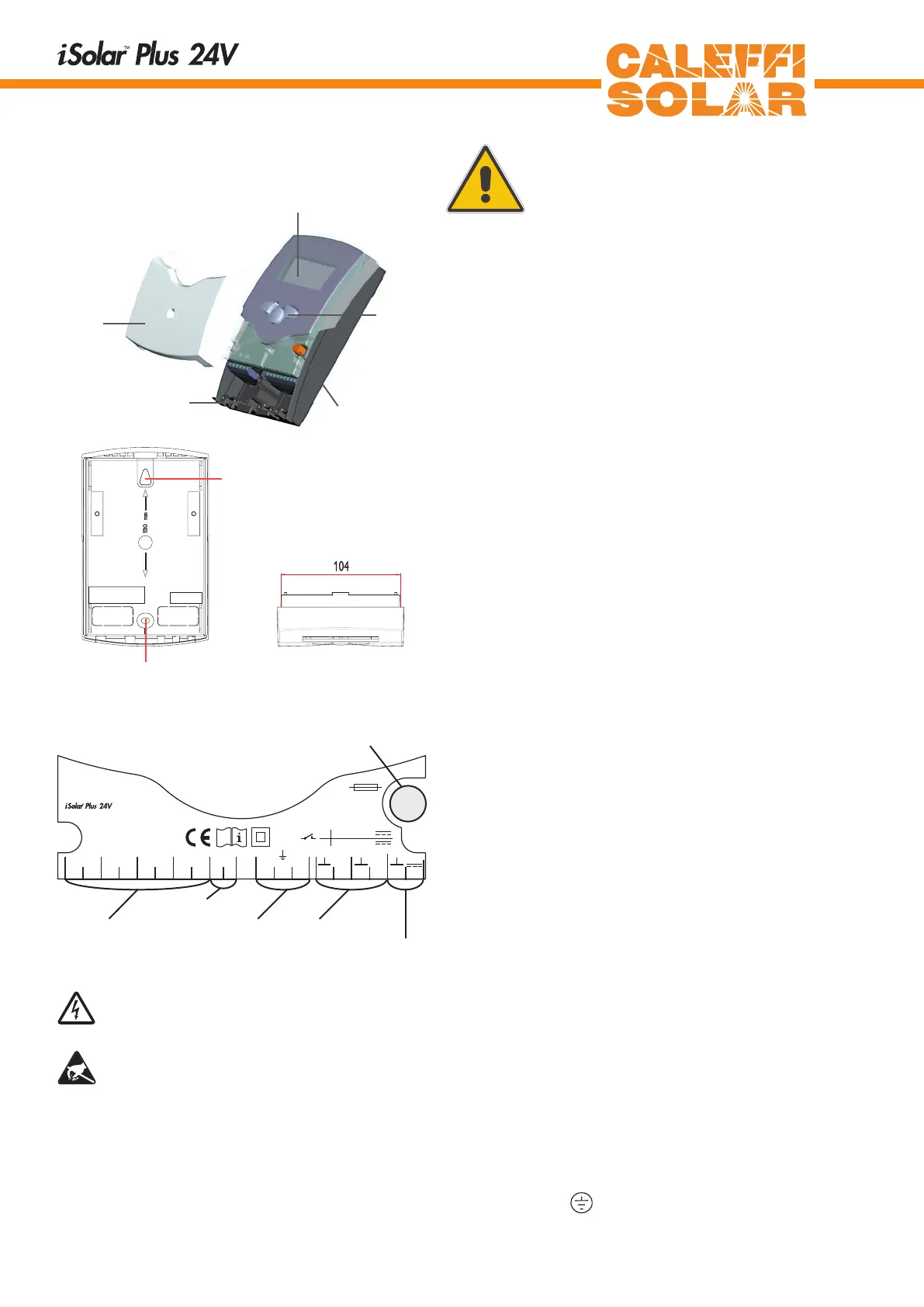
display
pushbutton
can fuse 4A
cable conduits with strain
relief
cover
12
S1 S2 S3
3456
Temp. Sensor
Pt1000
R1R2
201918171615
S4
78
141312
VBus
910
1 (1) A
1
24 V
(1) A 24V
R1
R2
T4A
24 V
CALEFFI
NORTH AMERICA, Inc.
Milwaukee,WI 53208
1.1 Mounting
This unit must only be located internally. It is not suitable
for installation in hazardous locations and should not be
sited near to any electromagnetic field. The controller must
additionally be equipped with an all-polar gap of at least 3 mm
or with a gap according to the valid installaton regulations,
e.g. LS-switches or fuses. Please ensure sensor cables and
ac power supply are separated
1. Unscrew the cross-head screw of the cover and remove
it from the housing.
2. Mark the upper fastening point on the subsurface
and premount the enclosed dowel and screw.
3. Mount the housing to the upper fastening point and mark
the lower fastening point on the subsurface (pitch of hole
130 mm), afterwards set the lower dowel.
4. Mount the housing to the top and fix it with the lower.
fastening screw.
.
1. Installation
Warning!
Switch-offpowersupplybefore
opening the housing.
1.2 Electrical connection
The power supply to the controller must only be made by
an external power supply switch (last step of installation!)
and the line voltage must be 24 Volt. Flexible lines are to
be fixed at the housing by enclosed strain relief supports
and screws.
The controller is equipped with 2 standard relays, to which
the consumers e.g. pumps, valves etc. can be connected:
• Relay 1
18 = conductor R1
17 = neutral conductor N
13 = ground clamp
• Relay 2
16 = conductor R2
15 = neutral conductor N
14 = ground clamp
The temperature sensors (S1 up to S4) will be
connected to the following terminals independently of the
polarity:
1 / 2 = Sensor 1 (e.g. Sensor collector 1)
3 / 4 = Sensor 2 (e.g. Sensor tank 1)
5 / 6 = Sensor 3 (e.g. Sensor collector 2)
7 / 8 = Sensor 4 (e.g. Sensor tank 2)
The power supply is effected to the clamps:
19 = neutral conductor N
20 = conductor L
12 = ground clamp
net clamps
fuse
consumer clampsSensor clamp
fastening
fixing
ground clamp
Electrostatic discharge can lead to damages of elec-
tronic components!
Dangerous voltage on contact!