© Caleffi 08301_iSolar Plus 24V.monus.indd
5 |
S1
S2
S4 / TRF
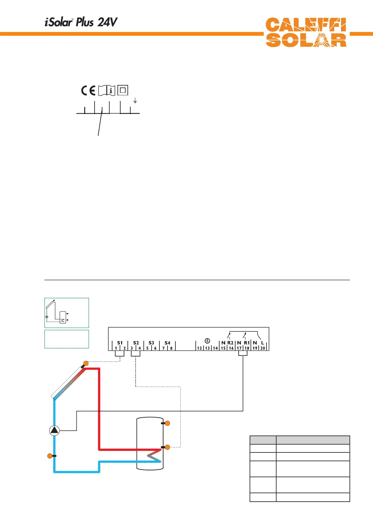
1.2.2 Allocation of clamps for system 1
Standard solar system with 1 tank, 1 pump and 3 sensors.
Sensor S4 / TRF can optionally be used for heat quantity
balancing.
R1
Arr 1
S3
1.2.1 Datacommunication/Bus
The controller comes with a VBus
®
for data communication
and energy supply of external modules. The connection
is effected with optional polarity at the clamps marked
with„VBus
®
“. Via this data Bus you can install one or more
VBus
®
modules, e.g.:
• heat quant. measurement module WMZ
• large display GA3
• Data logger, DL1
• Data teleindication, DFA2
Additionaly, the controller can be connected to the PC with
the help of a RS-COM adapter. With the ServiceCenter
Software (RCS) the controller parameters can be changed,
measurements can be read out, processed and visualised.
The software enables an easy function control and adjust-
ment of the system.
1 2
S1 S2 S3
3 4 5 6
Temp. Sensor
Pt1000
R1R2
201918171615
S4
7 8
141312
VBus
910
1 (1) A
1
24 V
(1) A 24 V
R1
R2
T4A
24 V
CALEFFI
NORTH AMERICA, Inc.
Milwaukee,WI 53208
VBus
connection clamps
Symbol Specification
S1 Collector sensor
S2 Tank sensor below
S3 Tank sensor at the top
(optionally)
S4 / TRF Sensor for heat quantity
measurement (optionally)
R1 Solar pump