General function
The printed circuit board (PCB) controls the heating and fi lling
functions of the boiler by monitoring the thermistor and level
sensors. The PCB also controls the external light unit to indicate
the current state of the boiler. Red and yellow LED’S on the circuit
board indicate whether the PCB has energised the element or
solenoid respectively.
Should an element fail and need to be replaced, it may be
necessary to replace the lid gasket to ensure a reliable steam-tight
seal. Note: the element has a permanent ‘Live’ feed, and the
‘Neutral’ is switched.
Printed Circuit Board replacement (PCB)
In the unlikely event of a PCB failing and a replacement being
required, full instructions will be supplied. It is important to note
however, that the Triac PCB must be securely mounted against the
copper heat-sink to ensure reliable heat dissipation. Heat transfer
compound is also supplied with all replacement circuit boards.
Adjusting the Water Temperature Set Point
The temperature potentiometer (Pot) is pre-set at Calomax and
will only require adjustment in exceptional circumstances. Contact
Calomax for advice.
Water boils at different temperatures depending on barometric
pressure. The temperature should not be tuned higher than 98
°C, or
over boiling may occur during low barometric pressure conditions.
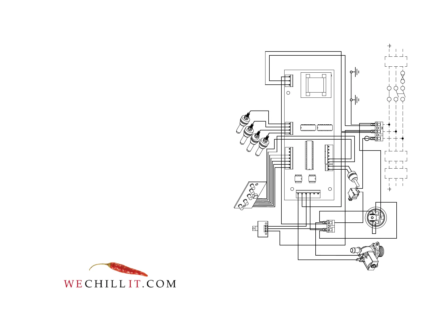
Wiring Schematic for
Eclipse
3W5, 3C5 &
3C10 Water Boilers
TRIAC PCB
RCD
INCOMING SINGLE PHASE SUPPLY THROUGH A
DOUBLE POLE ISOLATING SWITCH, FUSE AND
(RECOMMENDED) RCD DEVICE HAVING A RATED
OPERATING CURRENT NOT EXCEEDING 30mA
L
N
FITTED PLUG
& LEAD
RCD
L
N
COUNTER-TOP MODELSWALL-MOUNTING MODELS
COLD WATER INLET
SOLENOID VALVE
POWER
SWITCH
THERMISTOR
EARTH ON
WATER TANK
EARTH ON
WRAPPER
ELEMENT WITH
THERMAL CUTOUT
(NC)
LIGHT CIRCUIT BOARD
LOW
ECO
NORMAL
HIGH
LEVEL
SENSORS
GREY 0.75mm
GREY 0.75mm
BLACK 1.5mm
BLUE 1.5mm
WHITE 0.75mm
YELLOW 0.75mm
BLACK 0.75mm
RED 1.5mm
RED 1.5mm
ORANGE 0.75mm
GREEN 0.75mm
BROWN 0.75mm
PINK 0.75mm
RED
1.5mm
RED 1.5mm
BLACK 1.5mm
GREEN/YELLOW 1.5mm
INSULATION
LOOP
BLACK 0.75mm
GREEN 0.75mm
GREEN/YELLOW 1.5mm GREEN/YELLOW 1.5mm
RED 0.75mm
RED
PINK
BROWN
GREEN
ORANGE
YELLOW
BLACK