32 ImPulse IP Audio Routing & Mixing System Start Up Guide
12. EXAMINE AN EXAMPLE SYSTEM (SURFACE+CORES+DEVICES)
Pri Surface 192.168.24.190
Sec Surface 192.168.25.190
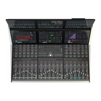
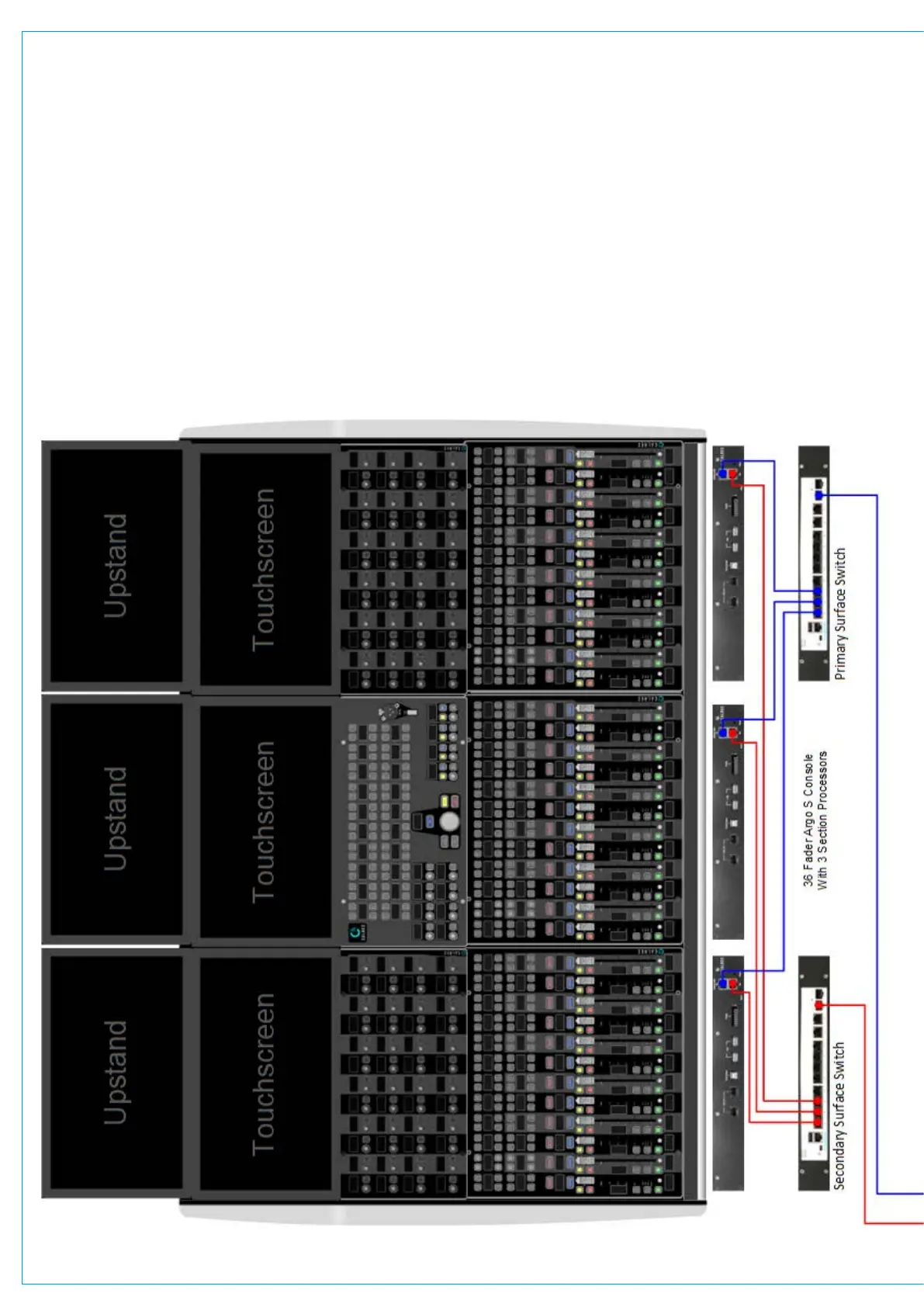
This example system is a 36 fader Argo S console surface, connected to a pair of Impulse cores using interface #3 shown in Blue for
Primary and Red for Secondary redundancy connections. The Impulse cores are connected to each other using Interface #5 shown
in Green to provide a redundant link. There are 2 PTPv2 aware audio switches providing audio redundancy. Each switch has its own
VLAN setup (Primary=VLAN30 and Secondary=VLAN31) for AoIP interfacing. All Primary AoIP traffic is on the 192.168.30/24
subnet and all Secondary AoIP traffic is on the 192.168.31/24 subnet. There are 3 Modular I/O Racks with AoIP interfaces and
in the case of Modular I/O rack 1, both AoIP Device interfaces have been used as the I/O count exceeds the nominal 256 limit per
connection. The Modular I/O Racks are connected to the single Router fitted in each core via the switches. All the required A ports
of each Router (primary & secondary cores) and Modular I/O rack AoIP Device interfaces are connected to the Primary audio switch
and all the required B ports of each Router (primary & secondary cores) and Modular I/O rack AoIP Device interfaces are connected
to the Secondary audio switch. The Connect Application can be accessed from interface #2 of the Primary core on 172.16.255.60
or when the Management subnet is configured from 172.29.1.21 or the Primary switch on 192.168.30.100 for setup via the PC.