S-Series Technical Manual 25 Cambridge Engineering, Inc.
shut-off high pressure regulator must be added
upstream of the heater’s individual low pressure
manual shut-off valve. If a high pressure regulator is
needed and has not been installed, check with your
local agent or Cambridge Engineering’s Customer
Service Group at 1-800-473-4569 to determine the
size and capacity requirements.
mWARNING:
When disconnect switch is activated with enclo-
sure open, live power is present. Only experienced
technicians with knowledge and respect for live
power should proceed beyond this point.
4. BLOWER ROTATION CHECK
a. Open the access door on the electrical control
enclosure side and turn the disconnect switch to the
“ON” position.
b. Turn the blower service switch to the “LOCAL”
position. Blower motor will start after the motor-
ized damper opens. Then, turn the blower service
switch to the “OFF” position and verify the blower
is rotating clockwise from the control enclosure
side.
IMPORTANT
On a three phase system, the rotation direction of
the blower may be reversed by switching any two
wires located on the downstream side of the motor
starter. The electrical supply to the heater must be
turned off prior to switching the wiring.
IMPORTANT
Indications of loose belts include barking or squeal-
ing when the blower starts. If these symptoms occur,
please refer to the Belt Tensioning instructions
(page 45)
IMPORTANT
The damper will remain in the open position as
long as the blower service switch is not returned to
the “REMOTE” position or the Low Temperature
Cutout (LTC) function has not timed out.
5. MOTOR AMP DRAW CHECK
IMPORTANT
The heater access doors must be closed for this test.
a. Turn the blower service switch to the “LOCAL”
position and let the motor warm up.
b. Check motor current at the overload on all three
legs.
c. Turn the blower service switch to the “OFF” posi-
tion.
IMPORTANT
The average amps must not exceed 103% of the
Motor Nameplate FLA. High amperage may indicate
excessive blower RPM.
6. BURNER MANIFOLD PRESSURE
ADJUSTMENT
a. Turn the disconnect switch to the “OFF” position.
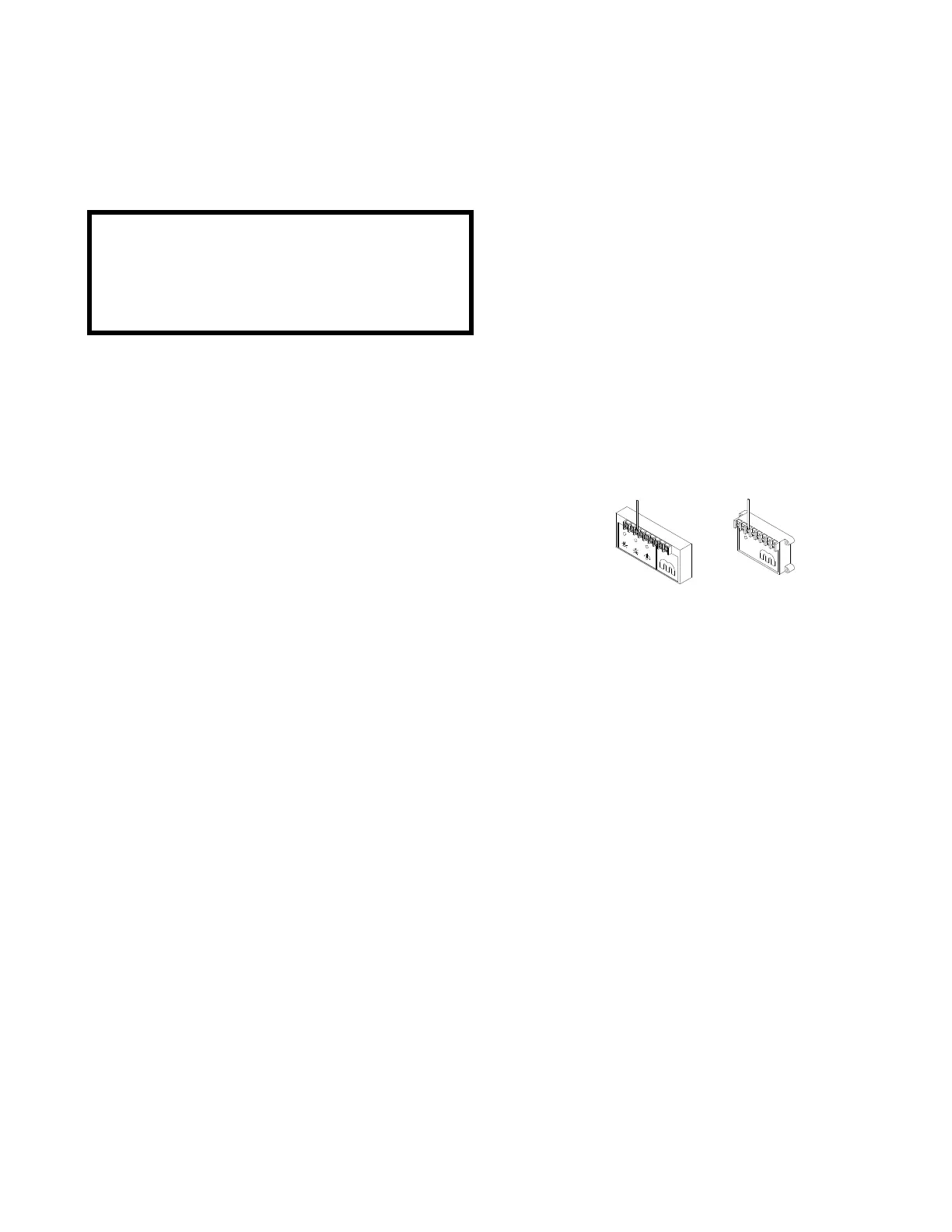
b. For EDL, EDR, EDSM, and EDSM/TP control
systems, remove the wire from terminal #3 on the
amplifier (see Figure 1). This will drive the modu-
lating valve to full open.
Figure 1
c. Remove the 1/8" plug from the manual shut-off
valve located just prior to the burner, and connect a
manometer for the purpose of measuring the mani-
fold pressure.
d. Refer to the heater nameplate for the Manifold
Differential Pressure (MDP) and record below.
e. Turn the disconnect switch to the “ON” position.
f. Turn the blower service switch to the “LOCAL”
position. The blower motor will start. Observe
the pressure reading on the manometer and record
below. (Note whether the reading is positive or
negative.)
g. Using the formula below, determine the required
manifold pressure reading for the manometer.
Nameplate MDP _______ " WC
Manifold Static Pressure
(Blower Only) + _______ " WC
Manifold Pressure Reading = _______ " WC