Cambridge Engineering, Inc. 26 S-Series Technical Manual
IMPORTANT
A negative manifold static (blower only) will cause
the manifold pressure reading to be lower than the
nameplate manifold differential pressure.
IMPORTANT
The high limit may trip on warm days. If this oc-
curs turn the blower on to allow the high limit to
cool. Turn the blower and burner service switches
to the "OFF" position. Access high limit and manu-
ally reset. Close the unit access doors and turn the
blower and burner service switches to the "LOCAL"
position.
h. Turn the burner service switch to the “LOCAL”
position. After a delay for prepurge and igniter
warm-up, the burner will light. Allow 15 seconds
for the low fire start to time out.
i. Observe the manometer reading and compare to the
manifold pressure determined above in Step 6.g. If
the manifold pressure reading does not equal this
value, adjust the control regulator until the proper
manifold pressure is obtained.
j. Turn the blower and burner service switches to the
“OFF” position.
k. Reconnect the wire to terminal #3 on the amplifier.
l. When performing a start-up proceed to the next
step, otherwise perform Final Heater Preparation
(page 29).
7. MINIMUM FIRE ADJUSTMENT
PROCEDURE
The minimum fire setting is preset at the factory at
approximately 20°F rise. This minimum fire setting
is not critical in space heating applications where the
heater is cycled in response to the space temperature
sensed by an operating thermostat. In this case, the
heater should operate at the maximum discharge tem-
perature, far from the minimum fire setpoint.
IMPORTANT
If a temperature rise of less than 15°F is desired,
a DC microammeter is required to monitor flame
signal during the adjustment procedure. Ensure
the flame current remains steady and of sufficient
strength to maintain burner operation for both con-
sistent ignition at minimum fire and locking in the
flame safeguard relay. Do not allow the flame signal
to drop below 2.0 microamps DC.
a. Turn the blower service switch to the “LOCAL”
position and monitor the discharge temperature.
b. On EDL, EDR and EDSM applications, remove the
wire from terminal #8 on the amplifier. This will
cause the burner to light on low fire and then fall to
minimum fire.
c. Turn the burner service switch to the “LOCAL”
position. After a delay for prepurge and igniter
warm-up, the burner will light. Allow 15 seconds
for the low fire start to time out.
d. Monitor the discharge temperature and flame sig-
nal. Subtract the temperature from step "7a" above
to determine the temperature rise. If the minimum
fire does not require adjustment, proceed to step
"7h".
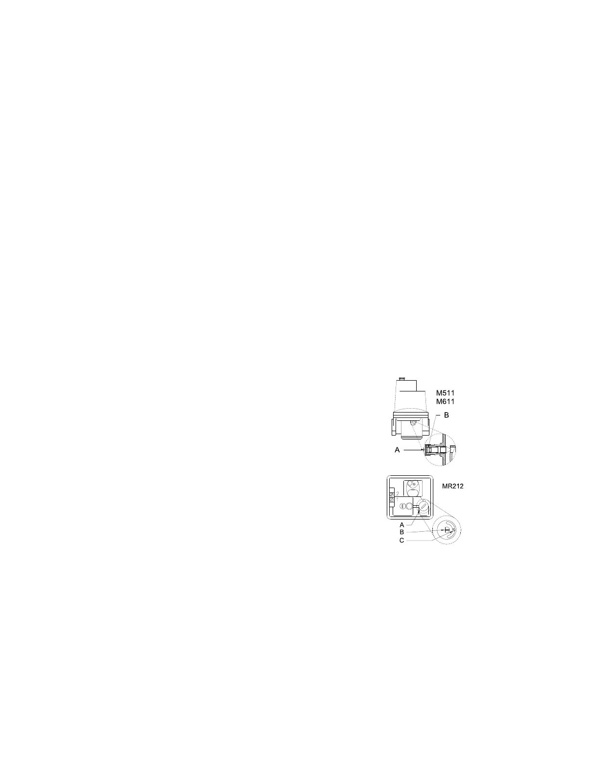
e. On the MR212 modulating/regulating valve,
remove the housing cover and loosen the lock
screw (C).
f. Remove the cap (A) exposing the minimum fire
adjusting screw. Turn the adjusting screw (B) to
obtain the desired minimum fire setting.
g. Replace the cap (A).
On the MR212 modulating/regulating valve,
tighten the lock screw (C) and replace the housing
cover.
h. Turn blower and burner service switches to the
“OFF” position.
i. Reconnect the wire to terminal #8 on the amplifier.
j. When performing a start-up proceed to the next