Cambridge Engineering, Inc. 30 S-Series Technical Manual
6. Carefully reinstall the DTS. Replace the Discharge
Air Temperature Sampling Box cover, and close
the unit access doors.
7. Turn the blower and burner service switches to the
“LOCAL” position. After a delay for the prepurge
and igniter warm-up, the burner will light. Allow 15
seconds for the low fire start to time out.
8. Wait for the discharge temperature and manifold
pressure to stabilize. Do not rush this step.
9. Repeat steps 1. through 8. pages 29-30 until the
manifold pressure and discharge temperature com-
ply with the guidelines of the Calibration Check
procedure step 8b. (page 27).
EDSM AND EDSM/TP
CONTROL SYSTEMS
(MAXITROL SERIES 44)
1. Remove the two mounting screws from the
Maxitrol A1044 Amplifier located in the Electrical
Control Enclosure. Refer to the Electrical Control
Enclosure Isometric Drawing (page 56) for addi-
tional information.
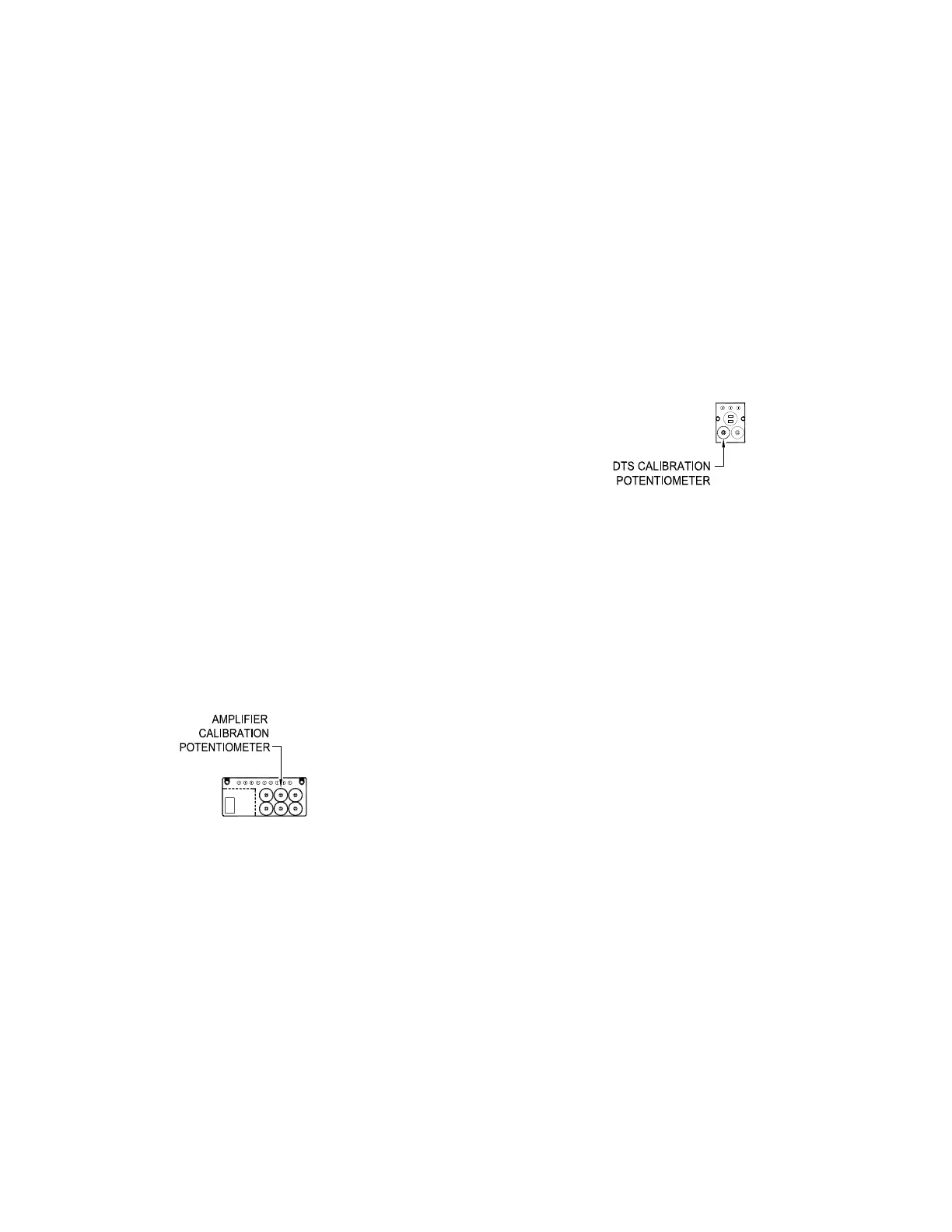
2. Turn the amplifier over and adjust the amplifier
calibration potentiometer shown in the drawing.
To raise the discharge temperature, use a Phillips
screwdriver to adjust the potentiometer counter-
clockwise. To lower the discharge temperature,
adjust the potentiometer clockwise.
3. Wait for the discharge temperature and manifold
pressure to stabilize after making adjustments. Do
not rush this step.
4. In rare cases, the amplifier calibration potentiometer
will reach its adjustment limit before the proper dis-
charge temperature is achieved. If this occurs, the
Discharge Temperature Sensor (DTS) will need to
be adjusted:
a. Turn the burner service switch to the “OFF” posi-
tion and allow the Discharge Air Temperature
Sampling Box time to cool.
b. Turn the blower service switch to the “OFF”
position.
c. Open the unit access door on the control enclo-
sure side.
d. Remove the access cover from the Discharge
Air Temperature Sampling Box and remove the
two mounting screws from the DTS. Refer to
the Individual Component Description Section
(pages 67-72) for additional information.
e. Carefully remove the DTS from the sampling
box, turn it over and adjust the DTS calibration
potentiometer shown in the drawing. To raise the
discharge temperature, adjust the potentiometer
90˚ counterclockwise.
f. Carefully reinstall the DTS. Replace the
Discharge Air Temperature Sampling Box cover,
and close the unit access doors.
g. Turn the blower and burner service switches to
the “LOCAL” position. After a delay for the pre-
purge and igniter warm-up, the burner will light.
h. Wait for the discharge temperature to stabilize.
Do not rush this step.
i. Repeat steps 4a through 4h until the manifold
pressure and discharge temperature comply with
the guidelines of the Calibration Check procedure
step "8b" (page 27).
5. Reinstall the amplifier that was removed in
step 1 (page 30).
EDR CONTROL SYSTEMS
(MAXITROL SERIES 14)
1. Turn the burner and blower service switches to the
“OFF” position.
2. Label and then remove the wires from terminals 1
through 3 of the Remote Heat Adjustment (RHA) in
the remote control station.
3. Remove the RHA from the remote control station.