S-Series Technical Manual 31 Cambridge Engineering, Inc.
Take the RHA to the unit control enclosure. See
Individual Component Description (page 70) for
RHA details, and Heater Configuration (page 4) for
electrical control enclosure location.
4. Remove the wires from terminals 21 and 22 of the
right-hand side of Terminal Block #1 in the unit
control enclosure. Connect these wires to terminals
1 and 3 of the RHA.
5. Place a jumper between terminals 2 and 3 of the
RHA.
6. For the single dial RHA, the jumper activates the
0 to 40°F override dial. Verify the override tem-
perature selector dial is set to 40°. Verify the dial
on the face of the RHA is set to 90° to obtain a set-
point of 130°.
For the dual dial RHA, the jumper activates the
Space Heat selector dial. Verify the Space Heat dial
is set to 160°.
7. Turn the blower and burner service switches to the
“LOCAL” position. After a delay for the prepurge
and igniter warm-up, the burner will light.
8. Wait for the discharge temperature and manifold
pressure to stabilize. Do not rush this step. Allow
15 seconds for the low fire start to time out.
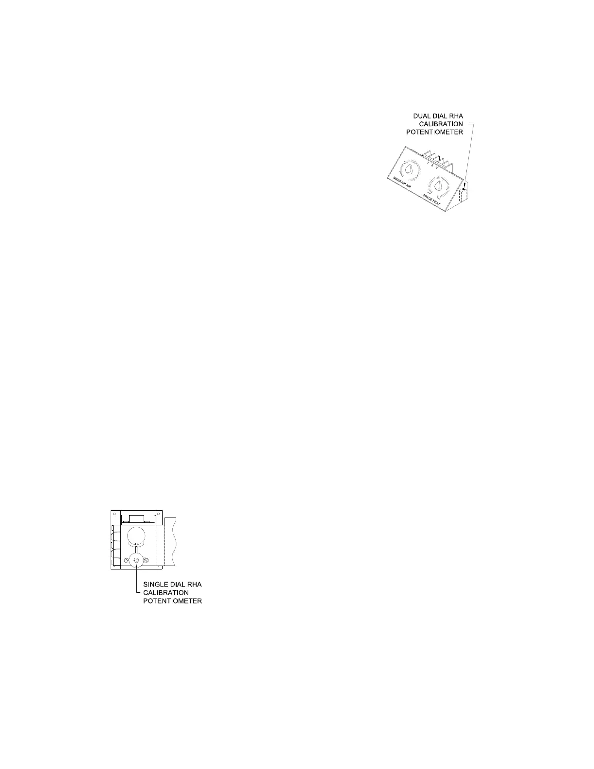
9. For the single dial RHA, adjust the calibration
potentiometer shown in the drawing. To raise the
discharge temperature, adjust the potentiometer
clockwise. To lower the discharge temperature,
adjust the potentiometer counterclockwise.
For the dual dial RHA, adjust the calibration poten-
tiometer shown in the drawing. To raise the discharge
temperature, adjust the potentiometer clockwise. To
lower the discharge temperature, adjust the potentiom-
eter counterclockwise.
10. Allow the discharge temperature and manifold
pressure to stabilize between adjustments until
the manifold pressure and discharge temperature
comply with the guidelines of the Calibration
Check procedure step "8b" (page 27).
11. Turn the burner and blower service switches to
the “OFF” position. Remove the wires from ter-
minals 1 and 3 of the RHA that were connected
in step 4. Reconnect the wires to terminal 21
and 22 of Terminal Block #1 in the unit control
enclosure. Leave the jumper in place that was
applied in step 5.
12. Return the RHA to the Remote Control Station.
Reconnect the wires that were removed in
step 2.
13. With the RHA reconnected in the Remote
Control Station, repeat steps 7 through 10. A
second technician and two-way communication
may be required.
14. Turn the burner and blower service switches to
the “OFF” position. Remove the jumper from
terminals 2 and 3 of the RHA if one was added
during step 5.