Pag. 6 - Manuale FB01348M4A - 01/2020 - © CAME S.p.A. - -
Dismantling and disposal
Dispose of the packaging and the device responsibly
at the end of its life cycle, in compliance with the
laws in force in the country where the product is
used. The recyclable components are marked with a
symbol and the material ID marker.
THE DATA AND INFORMATION IN THIS MANUAL MAY
BE CHANGED AT ANY TIME AND WITHOUT NOTICE.
THE MEASUREMENTS, UNLESS OTHERWISE STATED,
ARE IN MILLIMETRES.
Description
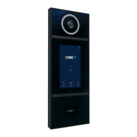
XVP S
Wall-mounted video intercom entry panel with touch
screen for IP360 system.
XVP F
Recessed video intercom entry panel with touch
screen for IP360 system.
Function of terminals
B
Local power supply input12 – 24 V DC
CAN BUS data line
Electric lock 12 V - 1 mA 12 V - 1 A max.
Earth
Door release button (NO)
Open door contact input (NC)*
Entry panel enabling output
*Active to earth
Max relay contact 1 A 30 V (AUX 2)
The contact can be programmed to perform
different functions.
Button for programming.
Press the PROG button to access the SETTINGS
section.
RESET button
When pressed it restarts the device.
This operation DOES NOT delete any programming
Technical data
MODELS XVP F XVP S
Dimensions for recess
mounting (mm)
153 x
406 x 15
-
Dimensions for wall
mounting (mm)
-
153 x
406 x 50
Packaging dimensions
(mm)
225 x 520 x 145
Packaging weight (kg) 3,3
Power supply (V) 12 – 24 DC
PoE power supply
IEEE 802,3at POE+
(25.5W)
Consumption in stand-by
mode (mA)
700
Operating temperature (°C) -40 ÷ +55
Protection rating (IP) 55
Protection rating (IK) 08
Video standard H.264
Display TFT 7"
Display resolution (pixels) 1024 x 600
Standard wireless Bluetooth LE 5.0
Radio frequency (MHz) 2400
Transmission power (dBm) 0
Proximity sensor range
(cm)
30 ÷ 130
The minimum on temperature from cold is
-25°C.
Recess-mounted installation
The wall must be perfectly flat and flush with
the box to reach the IP rating 55.
Wall in the box at the desired height
taking into account the TOP indication and the
positioning of the camera lens.
Eliminate one or more break points of the box.
Thread the pipe with the system conductors
through one of the break points.
Wall in the box.
For a better grip, push the fixing tabs
outwards.
Lower the bracket.
Hook the entry panel onto the support.
Remove the terminal cover.
Make the connections.
MTMRFID module installation (not provided)
Remove the module fastening bracket.
Make the connections to the entry panel
using the FLAT cable.
Position the module using the four pegs as a
centring unit.
Lock the RFID module fixing the bracket.
Fasten the bracket in one of the two positions,
depending on the thickness of the device.
If a third-party RFID device is installed,
replace the tag.
Fasten the front to the box using the screws
provided.
Position the cover strips.
To remove the cover strips, use the key provided.
Wall-mounted installation
The wall must be perfectly flat and flush with
the bottom of the box to reach the IP rating 55.
To remove the front part of the entry panel
from the box, use the key supplied.
Secure the box at the desired height
taking into account the TOP indication and the
positioning of the camera lens.
Eliminate one or more break points of the box.
Thread the pipe with the system conductors
through one of the break points.
Secure the box to the wall using the plugs
and screws supplied.
Lower the bracket.
Hook the entry panel onto the support.
Remove the terminal cover.
Make the connections.
MTMRFID module installation (not provided)
Remove the module fastening bracket.
Make the connections to the entry panel
using the FLAT cable.
Position the module using the four pegs as a
centring unit.
Lock the RFID module fixing the bracket.
Fasten the bracket in one of the two positions,
depending on the thickness of the device.
If a third-party RFID device is installed,
replace the tag.
Fasten the front to the box using the screws
provided.
Position the cover strips.
Remove the protective films on the glass.
S
To remove the cover strips, use the key provided.
This device complies with Part 15 of the FCC
Rules. Operation is subject to the following
two conditions:
1 - This device may not cause harmful
interference.
2 - This device must accept any interference
received, including interference that may
cause undesired operation.
This product contains FCCID: QOQBGM13P.
FRANÇAIS
Instructions générales pour
l’installateur
Lire attentivement les instructions avant de
commencer l'installation et d'effectuer les
interventions comme indiqué par le fabricant. •
L’installation, la programmation, la mise en service
et l'entretien doivent être effectués par du personnel
qualifié et dans le plein respect des normes en
vigueur. • Avant toute opération de nettoyage,
d'entretien ou de remplacement de pièces
détachées, mettre le dispositif hors tension. • Ce
produit ne devra être destiné qu'à l'utilisation pour
laquelle il a été expressément conçu et toute autre
utilisation est à considérer comme dangereuse.
• Le fabricant décline toute responsabilité en
cas d’éventuels dommages provoqués par des
utilisations impropres, incorrectes et déraisonnables.
• Ce produit est conforme aux directives de
référence en vigueur.
Mise au rebut et élimination
Ne pas jeter l'emballage et le dispositif dans la
nature au terme du cycle de vie de ce dernier, mais
les éliminer selon les normes en vigueur dans le
pays où le produit est utilisé. Le symbole et le sigle
du matériau figurent sur les composants recyclables.
LE CONTENU DE CE MANUEL EST SUSCEPTIBLE DE
SUBIR DES MODIFICATIONS À TOUT MOMENT ET
SANS AUCUN PRÉAVIS.
LES DIMENSIONS SONT EXPRIMÉES EN
MILLIMÈTRES, SAUF INDICATION CONTRAIRE.
Description
XVP S
Portier vidéo externe avec écran tactile pour système
IP360, mural.
XVP F
Portier vidéo externe avec écran tactile pour système
IP360, encastrable.
Fonction des bornes
Entrée alimentation locale12-24 VDC
Ligne données CAN BUS
Serrure de verrouillage électrique 12 V - 1 mA
12 V - 1 A max.
Masse
Bouton ouvre-porte (NO)
Entrée contact pour ouverte (NF)*
Sortie activation poste externe
*Activée vers la masse
Contact relais max. 1 A 30 V (AUX 2)
 Loading...