Do you have a question about the CAME AGT A200 and is the answer not in the manual?
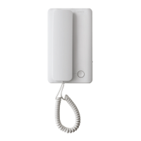
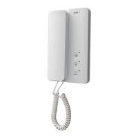
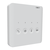
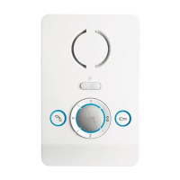
Details the AGT A200 as an internal audio receiver and its functionality.
Details the terminal connections and functions for the AGT A200's M1 board.
Provides step-by-step instructions for installing the AGT A200 device.
Explains the A/200R's features, including power supply and call generation.
Details terminal board functions and technical specifications for the A/200R.
Instructions for installing the A/200R unit on DIN rails or walls.
Details the HA/200 as an audio module and its terminal functions.
Presents technical specifications like power supply, consumption, and IP rating.
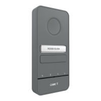
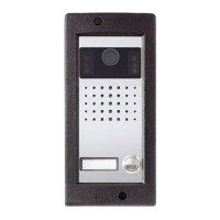
Lists various accessories for the TARGHA 200 system, including boxes and components.
Step-by-step guide for recessed installation of system components.
Instructions for mounting system components directly onto a wall.
How to recess multiple boxes horizontally or vertically.
Instructions for mounting multiple units side-by-side on a wall.
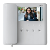
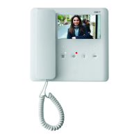
The CAME AGT kit A200 is a comprehensive audio intercom system designed for residential and commercial applications, offering a blend of functionality, ease of use, and modularity. The kit primarily consists of an internal audio receiver (AGT A200), an audio module (HA/200), and a power supply unit (A/200R), complemented by various accessories for flexible installation.
The AGT A200 serves as the primary indoor unit, allowing users to communicate with visitors at the entry panel and control access. Its main function is to provide clear audio communication. A key usage feature is the door lock release button, which can be configured to be active only when the handset is lifted, enhancing security by preventing accidental or unauthorized door releases. This configuration is achieved by cutting a specific jumper on the device, demonstrating a simple yet effective customization option. The terminal board on the AGT A200 facilitates essential connections, including earth, call input from the entry panel, and audio input/output to and from the entry panel.
Installation of the AGT A200 is designed to be straightforward. The device opens by pressing a tab at the bottom, allowing the shell to be separated from the base. The base can then be securely fastened to a wall box at an appropriate height for the user. It is important to avoid overtightening the screws during this process. Once all connections are made, the shell reattaches to the base, completing the installation. This modular design simplifies both initial setup and any future maintenance or troubleshooting.
The HA/200 is the audio module responsible for handling the audio signals within the intercom system. It includes a terminal board for various connections: power supply, +12 V DC output, common call for the call beep, audio to the internal receiver, audio from the internal receiver, and an enable terminal. A notable usage feature of the HA/200 is its flexibility in activation. In systems with an enable command, terminal 14 can be connected to earth to keep the unit always active, or to terminal 12 to activate the unit only when the handset is lifted. This allows for customization based on user preference and system requirements.
The HA/200 also incorporates trimmers for adjusting speaker and microphone audio levels, enabling users to optimize sound quality for their specific environment. This maintenance feature ensures clear communication by allowing fine-tuning of audio performance.
The A/200R is a crucial component that guarantees power supply to the HPC/1 entry panel and supports a significant number of front plates with multiple buttons. Its function extends beyond simple power provision, as it integrates several key features for system operation.
The A/200R provides two dual-tone call beeps, which can be used for two entry panels or for additional calls, such as from a landing. This enhances the system's ability to differentiate calls from various points. It also includes a power supply and control mechanism for a solenoid lock (12 V AC 1 A) via an integrated relay, offering secure access control. The call generator feature produces two types of dual-tone beeps and supports connecting up to three internal receivers in parallel on the same call, making it suitable for multi-user environments.
A versatile usage feature of the A/200R is its power flexibility; it can be powered at 12 V DC, allowing for connection to a battery or UPS for backup power, ensuring continuous operation even during power outages. It is important to note that the device does not include an auxiliary-input protection device.
For installation, the A/200R can be mounted on DIN rails within a suitable switchboard or directly on a wall using terminal covers. Proper fixing of power supply cables is essential to prevent stress, traction, or twisting. Dismantling the device is also clearly outlined in the manual. A critical maintenance consideration is that the power supply must always be installed horizontally, and correct ventilation must be ensured if it is installed in a metal case, to prevent overheating and ensure longevity.
The TARGHA 200 accessories provide a modular approach to building the entry panel, accommodating various installation scenarios and user needs. These accessories include recessed boxes, back-boxes, wall-mounted bases, blanking plugs, cable gland joints, spacers, screws, buttons, microcontacts, button springs, front plates, microcontacts with common call, lighting groups, and cable holders.
For recessed installation, the HTS recessed box must be flush-mounted into the wall at a suitable height, using provided spacers to prevent distortion. A notable usage feature is the option to mount the microphone remotely if the Larsen effect (audio feedback) occurs, demonstrating adaptability to challenging acoustic environments. To remove the microphone from its housing, a small screwdriver is used, taking care not to damage the cabling. Before inserting the microphone into the back-box, a specific part needs to be removed with pliers.
The audio group is inserted high up in the back-box. Microcontacts are fitted into their correct housings. The front plate is equipped with a common call for microcontacts, allowing for up to four additional buttons to be installed. The lighting group is then inserted into its housing. Protective seals on the recessed box holes are removed, and the back-box is attached using screws. Connections are made, and cables are secured with cable holders, which should be located near the audio group.
For wall mounting, two blanking plugs are fixed to the base. The recessed box (or a round Ø 65 mm box) is attached flush with the wall at a suitable height, using screws and expansion plugs. Similar to recessed installation, the microphone can be mounted remotely if the Larsen effect occurs. The process of removing the microphone from its housing and preparing the back-box is identical. The audio group, microcontacts, and lighting group are installed as in recessed mounting. Connections are made, and cables are secured with cable holders.
For button assembly, the name card holder and card are removed to write desired information. Personalized name cards up to 2 mm thick can be used, offering a customizable usage feature.
To close the front plate, the upper part is inserted into the top, and a locking screw is tightened with a 2.5 hex key, ensuring a secure and finished look.
For side-by-side recessed installation, blanking plugs are removed, and cable gland joints are inserted. The recessed boxes must be walled in flush with the wall at a suitable height, using spacers to prevent distortion.
For side-by-side wall mounting of entry panels, two blanking plugs are inserted into the exposed sides, and cable gland joints are placed at the bottom and top. The assembled bases are then attached to the wall using screws and expansion plugs.
Overall, the CAME AGT kit A200 is designed for robust performance and flexible installation, catering to various needs with its modular components and user-friendly features. The emphasis on clear installation instructions and adaptable configurations makes it a versatile choice for intercom systems.
| Brand | CAME |
|---|---|
| Model | AGT A200 |
| Category | Intercom System |
| Language | English |